Technical Field
The invention relates to automobile production field, in particular, relates to a stepless transmission used for a direct drive hydraulic device and automobile for continuously-variable transmission.
Background Art
With the progressive development of the automobile industry, is of the automatic transmission is gradually increase in capacity, in particular, as the continuously variable transmission in the automatic transmission, to a leap in development. Stepless speed variator with the common hydraulic automatic transmission the most important difference is that, by using the continuously variable transmission with the main transmission belt, the friction force between the driven wheel the power of the driving wheel is transmitted to the driven wheel, the clamping hydraulic device provides the transmission belt. Has the advantages of smaller size, simple in structure, can freely change the drive ratio, the more stable speed change, there is no traditional transmission shift when the feeling of "accent".
The speed ratio of the continuously variable transmission of a car by the main control also, control the clamping force of the driven wheel, thus the main, the driven wheel of the oil pressure control precision direct impact on the function of vehicle stepless speed change gear and transmission efficiency is realized. In in prior art hydraulic control device for the main in the stepless speed change process, the control precision of the driven wheel set low, the corresponding slow, complicated structure.
Content of the invention
The purpose of this invention is to provide for a continuously variable transmission and a direct drive hydraulic device for stepless speed changer for an automobile, in order to solve in the prior art hydraulic control device to the stepless speed changer speed varying process control accuracy is poor, the technical problem of slow response speed.
To achieve the above object, according to one aspect of the invention, provides for a continuously variable transmission a direct drive hydraulic device, including the active pressure control valve and a driven pressure control valve, the active pressure control valve, and control of the continuously variable transmission a driving gear unit is connected with the drive cylinder, for controlling the pressure of the drive cylinder; a driven pressure control valve, and control of the continuously variable transmission is connected with the driven cylinder, for controlling the pressure of the slave cylinder, the driven pressure control valve provided at a driven pressure control valve of the electromagnetic coil assembly and the driven the valve core, the valve core on the driven the electromagnetic coil assembly of the pressure control valve to drive the lower edge of the inner wall of the sliding; active pressure control valve includes the active pressure control valve is active and in active electromagnetic coil assembly, active valve core in the active electromagnetic coil assembly of the active pressure control valve to drive the inner wall of the lower edge of the slide.
Furthermore, active pressure control valve also comprises a driving armature, the driving armature, accommodated in the one end of the active electromagnetic coil, the other end extends out of active electromagnetic coil group and is fixedly connected with the driving valve.
Furthermore, active pressure control valve also comprises a driving spring, the driving spring, the 1st end is connected to the active pressure control valve on the inner wall of the end of the 1st, 2nd end on the active end face of the valve core.
Furthermore, the driven pressure control valve also includes the driven armature, the driven armature, a driven end is received in the electromagnetic coil, the other end extends out of the driven the electromagnetic coil assembly and is fixedly connected with the driven valve.
Furthermore, the driven pressure control valve also includes a driven spring, the driven spring, is sleeved on the driven the valve core and the driven armature sunny, the 1st end of the side wall of the driven the electromagnetic coil, the other end is supported on the side wall of the driven valve.
Furthermore, active pressure control valve also includes an active valve, the active valve faces of the valve body are arranged at intervals on the inner wall of the side wall of the two the two symmetrical ring groove ring groove is interface 5th, 6th ring groove interface ring groove, the ring groove interface 7th, 8th ring groove interface ring groove, the ring groove 5th, 6th ring groove, the ring groove 7th, 8th are respectively on the ring groove is provided with a through hole; a driven pressure control valve also includes a driven valve body, driven valve body faces the driven valve are arranged at intervals on the inner wall of the side wall of the two interface ring is ring 1st, 2nd ring groove interface ring groove, the ring groove interface 3rd, 4th ring groove interface ring groove, the ring groove 1st, 2nd ring groove, the ring groove 3rd, 4th ring groove are respectively equipped with a through hole; the ring groove interface of the 3rd, 4th and 7th ring groove interface ring through the ring groove interface 2nd output node is connected with the driven cylinder; 6th and 8th ring groove interface ring through the ring groove interface output node and 4th is connected with the drive cylinder.
Furthermore, also includes 1st output node, the output node 3rd, oil tank, lubrication oil source hydraulic oil source and, through the ring groove 1st 1st output node is communicated with the hydraulic oil source; 2nd 3rd output node through the ring groove and is communicated with the lubricating oil source; 5th annular groove is communicated with the oil tank.
Furthermore, the active valve core through 7th 1st step is arranged on the push surface; 3rd ring groove to the driven the valve core is provided with a 2nd step push surface.
Furthermore, active pressure control valve is a pressure reducing valve; a driven pressure control valve is an overflow valve.
According to another aspect of the invention also provides a hydraulic device adopting the above-mentioned of the continuously variable transmission of a car.
The invention has the following beneficial effects:
The present invention provides for continuously variable transmission of a direct drive hydraulic device, through the electromagnetic coil is energized and the magnetic force produced by the oil pressure produced by the oil pressure in the role each other, adjusting the control valve to achieve a balance in the movement of the valve core, so as to realize the moving cylinder and the pressure control of the drive cylinder. oil duct the device is simplified. The movement of the valve control of the magnetic force, so that the driven-pressure control valve and the active pressure control valve having the higher pressure control precision and the speed-changing instruction more rapid response capability. Speed speed ratio and in the process of the high precision of the control of the clamping force, variable speed reaction is fast
The device used for the hydraulic system has simple structure of the stepless transmission, and the speed ratio of the variable speed in the process of the high precision of the control of the clamping force, variable-speed fast reaction.
In addition to the above the purpose of the description, features and advantages, the invention also has other objectives, features and advantages. Will be with reference to Figure, this invention for further detailed description.
Description of drawings
Form a part of this application the Figure this is used to provide further understanding of the invention, illustrative embodiments of the invention the note for the interpretation of this invention, does not constitute the limits of this invention. On the drawings:
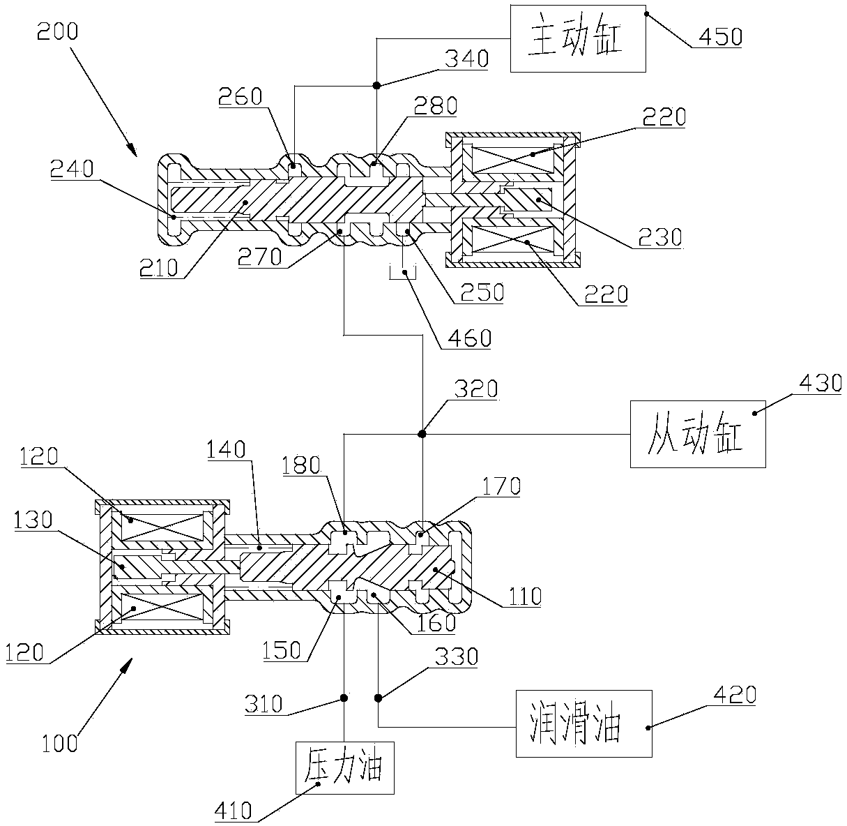
Figure 1 is a schematic diagram of direct drive hydraulic device of the embodiment of the present invention is preferably used for stepless speed changer.
Key note:
100, from the wheel pressure control valve; 110, driven valve core; 120, driven electromagnetic coil assembly; 130, the driven armature; 140, the driven spring; 150, annular groove 1st; 160, 2nd ring groove; 170, 3rd ring groove; 180, 4th ring groove; 200, driving wheel pressure control valve; 210, the active valve core; 220, active electromagnetic coil assembly; 230, the driving armature; 240, driving spring; 250, annular 5th; 260, 6th ring groove; 270, 7th ring groove; 280, 8th ring groove; 310, output node 1st; 320, 2nd output node; 330, output node 3rd; 340, output node 4th; 410, hydraulic oil source; 420, lubrication oil source ; 430, the driven cylinder; 450, active cylinder; 460, the fuel tank.
Mode of execution
The following illustrated in the Figure the embodiment of the present invention to carry out a detailed description, however, the invention is defined by claims and covers the implementation of a plurality of different ways.
See Figure 1, the present invention provides for continuously variable transmission of a direct drive hydraulic device which comprises a driven pressure control valve 100, active pressure control valve 200, hydraulic oil output node and the output node and is connected with a hydraulic oil of the connecting line of the valve. Active pressure control valve 200, and control of the driving wheel set stepless transmission of active cylinder 450 is connected, is used for controlling the cylinder 450 pressure. The driven-pressure control valve 100, and the control continuously variable transmission driven wheel of the driven cylinder 430 is connected, is used to control slave cylinder 430 pressure. Active pressure control valve 200 is provided with a drive valve core 210 and active electromagnetic coil assembly 220. Active electromagnetic coil assembly 220 can be of the magnetic force produced by the active valve core 210 the slide in the valve body. Inflows and outflows so as to regulate the active pressure control valve 200 of the flow rate of pressure oil. The play adjusting active cylinder 450 the action of the pressure of the pressure oil. Role of magnetic force can be accomplished through the medium, the medium can be a drive structure such as the armature or the other commonly used structure. The driven-pressure control valve 100 of the regulating process and the active pressure control valve 200 of the same, is omitted here. Pressure is adjusted by the electromagnetic force, can realize the linear regulation of the pressure, reduced in the process of speed regulation the kanton the appearance of the phenomenon, the speed of the improving the precision of the speed.
From the wheel pressure control valve 100 comprises in turn driven in the valve body to distribute the driven the electromagnetic coil assembly 120, the driven armature 130, the driven spring 140, driven valve core 110 and faces the driven valve core 110 on the driven the inner wall of the valve body situated at intervals a series of driven annular groove. In the 1st end of the valve body is provided with a driven armature 130. Driven electromagnetic coil group 120 around a driven armature 130 and hold the end of the 1st to the driven valve. A driven armature 130 is connected to the 1st driven the inner wall of the valve body end, the driven armature 130 of the end of the 2nd driven valve core 110 is connected, the driven armature 130 movement, can push the driven valve core 110 motion. Driven valve core 110 of the valve body accommodated in the end of the 2nd. A driven armature 130 and the driven valve core 110 is provided with a driven spring connection sleeve 140. The driven spring 140 is connected to the end of the 1st set of the block of the inner wall of the valve body, the driven spring 140 is connected to the end of the 2nd spool 110 on the end surface of. The driven spring 140 is compressed the valve spool 110 to the right the force of the movement.
The driven ring groove including 1st ring groove 150, 2nd ring groove 160, 3rd ring groove 170 and 4th annular groove 180. 1st ring groove 150, 2nd ring groove 160, 3rd ring groove 170 and 4th annular groove 180 a through hole are arranged on. Through the through-hole of the oil ring groove the flow is allowed to flow out, the flow of the oil on the basis of the pressure size motion. 1st ring groove 150 through the 1st output node 310 with the hydraulic oil source 410 is connected with the. 2nd ring groove 160 through the 3rd output node 330 and lubricating oil source 420 is connected with the. 3rd output node 330 the pressure oil as lubricating oil for the continuously variable transmission to lubricate the lubricating points. 3rd ring groove 170 and 4th annular groove 180 at the same time with 2nd output node 320 is connected with the. 2nd output node 320 also with the driven cylinder 430 and driving wheel pressure control valve 200 is connected with the.
Driving wheel pressure control valve 200 includes an active valve body and accommodated in the active in the valve body in the active valve core 210, active electromagnetic coil assembly 220, active armature 230, the active spring 240 and faces the active valve spool 210 of the valve body situated in the annular groove. Active spring 240 is connected to one end of the inner wall of the active valve, the active spring 240 and the other end of the valve core 210 is fixedly connected. Active spring 240 is in a compressed state. Active valve core 210 is mounted on the end of the 1st of the valve body. Active valve core 210 is sleeved in the end of the 1st of the active spring 240 and the inner wall of the active valve, the active valve core 210 2nd end of the driving armature 230 is connected. Active electromagnetic coil assembly 220 is fixed to the active armature 230 for the periphery of the valve body and hold the end of the 2nd. Active valve faces 210 of the intervals on the inner wall of the valve body is provided with a 5th annular groove 250, 6th ring groove 260, 7th annular groove 270, 8th ring groove 280. 5th interface ring groove 250, 6th interface ring groove 260, 7th interface ring groove 270, 8th interface ring groove 280 is respectively provided with a through hole. Through the through-hole of the oil ring groove the flow is allowed to flow out, the flow of the oil on the basis of the pressure size motion. 7th annular groove 270 and 2nd output node 320 is connected with the. 5th annular groove 250 and can hold the oil tank of the hydraulic oil 460 is connected with the. 6th ring groove 260 and 8th ring groove 280 with the 4th output node 340 is connected with the. 4th output node 340 and the driving cylinder 450 is connected. Active valve core 210 is the 7th annular groove 270 is close to the active electromagnetic coil group 230 is larger than the cross-sectional area of the side far away from the active electromagnetic coil group 230 of the cross-sectional area. 1st push surface of the step is formed. In order to return into the active pressure control valve 200 of the hydraulic oil to the active valve core 210 generates the thrust to the right. The valve core and 210 sensitivity to pressure.
When in use, under the condition of not being powered on are as follows: the pressure control valve by the driven wheel from the driving wheel to control the tension of the transmission belt. Hydraulic oil source 410 through the 1st hydraulic oil in the output node 310 enter the 1st ring groove 150, the hydraulic oil enters the driven valve body from the 4th annular groove 180 to leave through the 2nd output node 320 3rd overflowing into the annular groove 170. Since the positive to the 3rd ring groove 170 of the driven spool 110 of the valve body away from the one side of the end surface close to the cross-sectional area greater than the sectional area of the end face of the driven valve, 2nd form pressure can push surface of the step. At this moment, the driven spring 140 produce greater spring-back force, the driven valve core 110 reaches the right most large pole spacing. From the 3rd ring groove 170 to return to the hydraulic oil pushes the step in the face of the driven spool 110 to the left of the generated thrust force, the driven spring 140 the thrust to the right produced by the phase equilibrium, the driven valve core 110 produces the movement. Because the driven spring 140 will always be a spring-back force is generated, thus 2nd output node 320 will be the pressure value is not zero, therefore the driven cylinder 430 of the hydraulic in will not be zero, thereby ensuring that the transmission belt tension always exists from the wheel, to prevent slipping. In order to maintain the 2nd output node 320 pressure value is stable, when the 1st output node 310 hydraulic is too high, the driven pressure control valve 100 is increased by the thrust to the right, so as to increase the overflow flow, the purpose of protecting the transmission belt.
Is energized, the driven the electromagnetic coil assembly 120 generates a magnetic force, the armature 130 to move to the right, with the changes in the magnitude of current, changes in the driving force, 3rd ring groove 170 is 150 to 160 will change with the opening, so that the 2nd output node 320 and increase the pressure at the. Because the magnitude of the electric current change through 2nd output node 320 of the pressure, so as to realize the linear voltage regulation. When the 2nd output node 320 at the pressure of the transmission belt tension from the need of the driven wheel, a driving wheel pressure valve to the pressure transmitted into the 7th annular groove 270. When not being powered on, the active spring 240 in the longitudinal direction of the active valve core 210 generates the driving force to the right. Enter the 7th annular groove 270 8th of the hydraulic oil from the annular groove 280 leave, in 4th output node 340 to produce pressure flows back into the 6th ring groove 260, back to the hydraulic oil to the active valve core 210 generates the driving force to the right. The surplus hydraulic oil can be through the 5th annular groove 250 backflow to enter the oil tank 460. Active valve core 210 reach the right limit. Active spring 240 of the persistence in the longitudinal direction is generated, the output node 4th 340 of the pressure will not be zero. Is energized, driving the electromagnetic coil assembly 220 generates a magnetic force, an armature 230 and then push the active valve core 210 to move left, regulating backflow into the 6th ring groove 260 of the hydraulic oil, so as to regulate the output node 4th 340 of the pressure, thereby realizing the active cylinder 450 linear regulation of the pressure.
In another embodiment, from the wheel pressure control valve 100 of the overflow valve. Can improve the speed-regulating accuracy and speed.
In another embodiment, the driving wheel pressure control valve 200 is a pressure-reducing valve. Can improve the speed-regulating accuracy and speed.
In another embodiment, the hydraulic oil source 410 can not through the 1st output node 310, directly and the valve body is communicated with the corresponding ring groove. Lubricant source 420 by 3rd output node 330, directly and the valve body is communicated with the corresponding ring groove.
In another embodiment, may not be provided to promote surface and 2nd 1st step push surface of the step, the same purpose of this invention can be realized.
Another aspect of the present invention also provides a use of the hydraulic device for stepless transmission for vehicles. Transmission belt in the transmission can be continued to maintain tension of the driven wheel, speed regulating corresponding fast, accurate.
Above for the stated example the preferred embodiment of the invention, is not used for limiting of the present invention, the technical personnel in this field, the invention can have various modification and change. Where in the present invention within the spirit and principle of the, any modifications made by the, equivalent replacement, improved, and the like, shall be included in the scope of protection of this invention.
Direct driving type hydraulic device for stepless transmission and automobile stepless transmission






 400-4929-0909
 contact@catarc.com.cn

