Background Technology
In automobile manufacturing, the main method for connecting two parts into one is through screw joints. When two parts that do not require high-strength connections, especially those made of plastic or rubber or other non-metallic materials, still using screw joints is cumbersome and laborious, so clips are preferred.
In the prior art, taking the connection between sheet metal and door trim panels as an example, the door trim panel buckle assembly is used to connect the sheet metal parts and the door trim panel; The door trim panel buckle assembly includes a card located on the sheet metal part and a clip limited by the card holder. When in use, the clip limits the door trim panel, allowing the door trim panel to be mounted on the sheet metal part.
The card holder has a stop for the limit clip, which has a limit end that engages with the card holder. When in use, the limit end of the clip can be pushed along the opening of the stop to complete the installation of the door trim panel clip assembly. When assembling the door trim panel on sheet metal parts, it can be pushed into the latch connection end through the corresponding mounting hole on the door panel; In this structure, the limiting end is clamped onto the holder, preventing the clip and holder from shifting perpendicular to the direction of the locking opening. However, since the stopping is used not only for assembling the clip but also for limiting the clip, it protrudes inward at the opening of the stop to form a retaining edge, making the inlet size of the stopper smaller, so that after the clip and holder limit match, the clip and holder are stopped from shifting outward; Due to the presence of the flange, the two fitting components are assembled by compression at the flange position of the stop. On one hand, assembly is difficult, on the other hand, assembly damage is likely, and assembly reliability is likely, with the clamp and latch separated; Moreover, this prefabricated snap-fit assembly with a limiting function has strict requirements for assembly dimensions. If there is an abnormal dimensional error in one component (if the flange size is too large or too small, the clip is difficult or even ineffective to assemble, or vice versa), it will cause assembly failure of both components, making it difficult to control product quality and yield.
Therefore, to solve the above problems, a rotary snap-fit assembly is needed that can optimize the clasp assembly structure in the prior art, overcome the defects of current snap-fit assembly structures, and improve the finished product rate of assembly parts.
Summary of the utility model
In view of this, the purpose of this utility model is to overcome the defects in the prior art by providing a rotary snap-fit assembly that can optimize the clasp assembly structure in the prior art, overcome the defects of the current snap-fit assembly structure, and improve the finished product rate of assembly parts.
The rotary latch assembly of this utility model includes a clamping seat and a latch, the clamping seat is provided with an inlet port, and the latch has a limiting end; The block is arranged around the inlet port, which has a guiding surface facing the inlet;
During use, the clip extends into the holder through the inlet port via the limiting end, and by rotating, the limiting end passes through the guiding surface and is restricted by an obstacle to the holder.
Furthermore, the root of the obstacle is arranged on the bracket, with the head of the obstacle protruding from the bracket;
The guiding surface includes a curved or inclined surface formed inward from the root of the obstacle toward the head.
Furthermore, the obstacle also has a stop surface at an angle to the guiding surface. The stop turning surface is located behind the guide surface in the direction of rotation of the limit end, and after passing through the guide surface, the limit end is constrained by the obstacle's stop turning surface.
Furthermore, the limiting end has relative upper and lower limiting surfaces. After the limiting end extends into the inlet port, the upper limiting surface is located on the outer end face of the inlet port, and the lower limiting surface is located on the inner end face of the inlet port; By rotating the clip, the limiting end is arranged on the holder in a clamping manner through the limiting surface and the lower limiting surface.
Furthermore, the cross-section of the limiting end is shaped like the character "工" (工), with the bottom surface of the upper flange plate in the "工" shape serving as the upper limit surface, and the top surface of the "工"-shaped lower flange plate as the lower limiting surface. When in use, the opening of the "工" shape clamps the holder.
Furthermore, the inlet has long and short sides of varying lengths and sizes;
The length of the "G"-shaped lower flange plate is between the length of the inlet and the short side dimensions. The width of the "G"-shaped lower flange plate does not exceed the short side dimensions of the inlet, while the length of the upper flange plate in the "G" shape exceeds the short side size of the inlet;
This allows the lower flange plate of the limit end to extend into the inlet during use, and after being driven to rotate, the bracket is clamped through the "工" (work) opening of the limit end.
Furthermore, the holder includes a mounting plate, with an entry opening on the mounting plate, and the obstacle is formed by the bottom side of the mounting plate protruding downward;
The lower flange plate has a transition surface located at its upper edge;
During use, the transition surface passes through the guide surface, and the lower flange plate is restricted by obstacles.
Furthermore, the holder further includes a clearance chamber located inside the mounting plate, with an inlet opening connecting the mounting plate and the clearance chamber, and the lower flange plate being driven to rotate inside the clearance chamber.
Furthermore, the obstacle includes at least a pair of opposing positioning protrusions, each of which has a guiding surface facing the inlet port;
The side of the pair of limit protrusions opposite the bottom surface of the mounting plate forms a limit groove for limiting the lower flange plate.
Furthermore, the latch also has a snapping end used to snap and assemble preset components onto the latch.
The beneficial effects of this utility model are: the rotary latch assembly disclosed by this utility model improves the fit between the holder and the clip. The clamp is positioned around the holder by the retaining edge of the inlet port, so that after being confined to the holder, the clip does not detach from the holder circumferentially at the entry port. By installing obstacles, the limiting end of the clip passes through the guiding surface and is restricted to the holder. In this state, the clamp assembly direction limits the clip, preventing the clip from swinging or rotating, thereby fixing the holder and clip; The assembly process of the latch and holder in this solution is optimized from plug-in fitting to rotational fit, which does not damage the structure of the clip and holder, and assembly is simple. At the same time, the fit accuracy between the clip and holder is reduced, and there are no strict dimensional limitations, allowing effective control of product quality and yield.
Specific embodiments
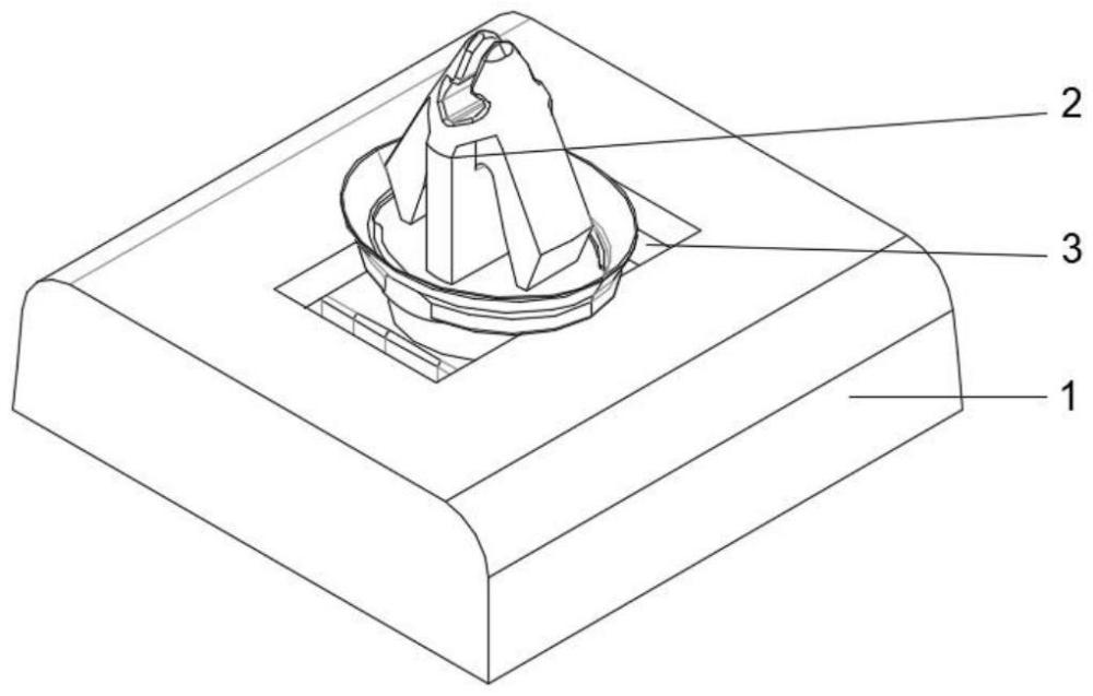
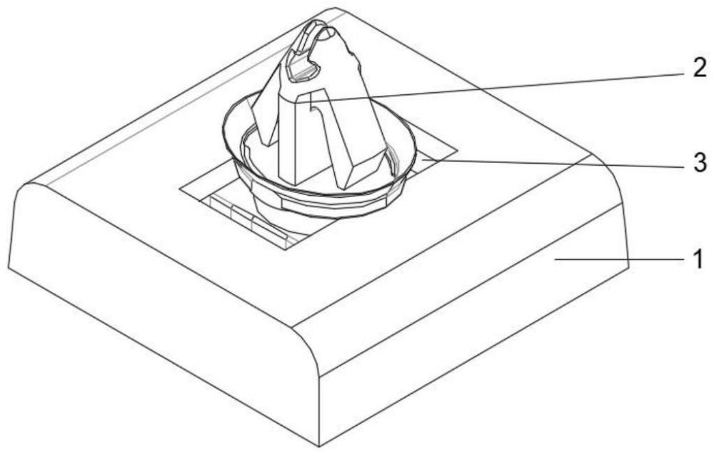
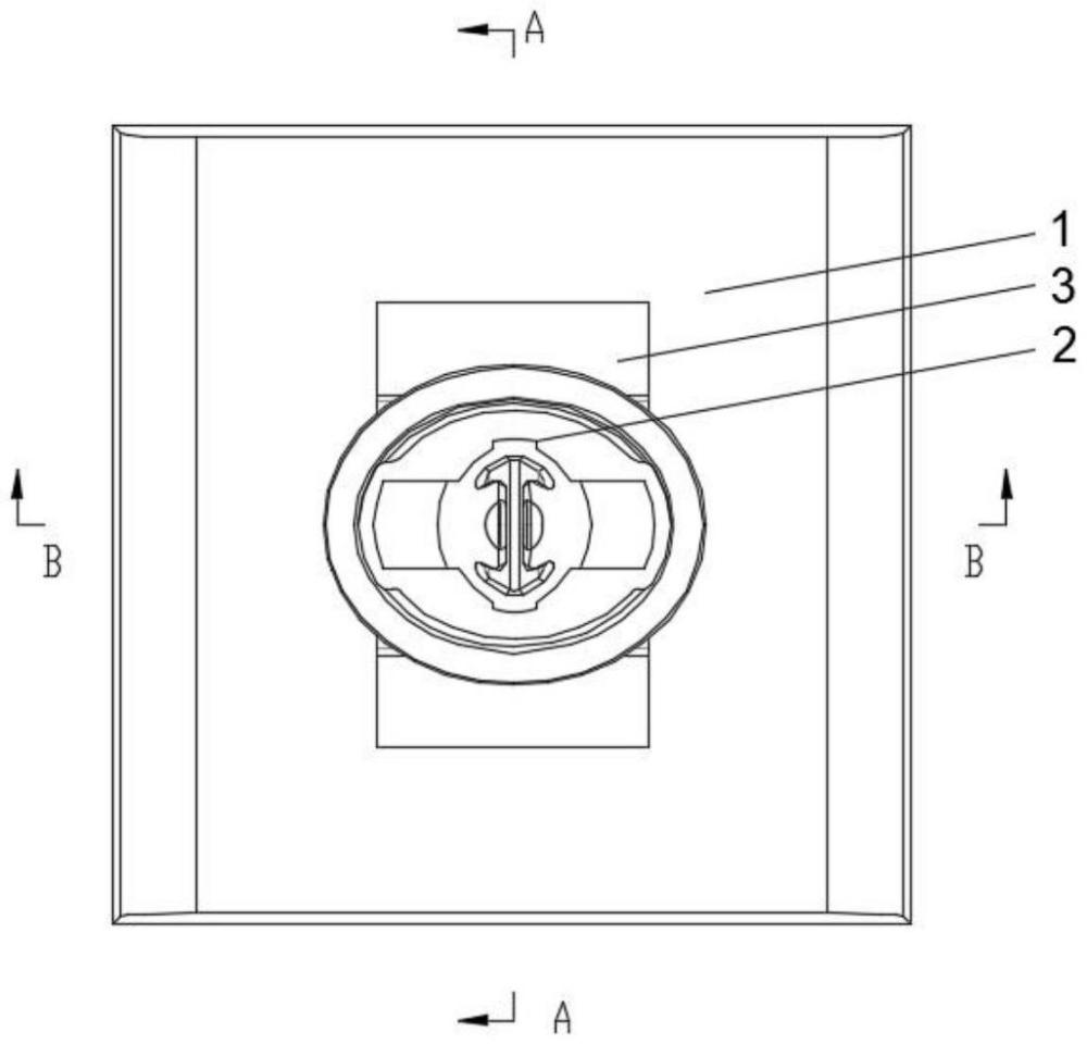
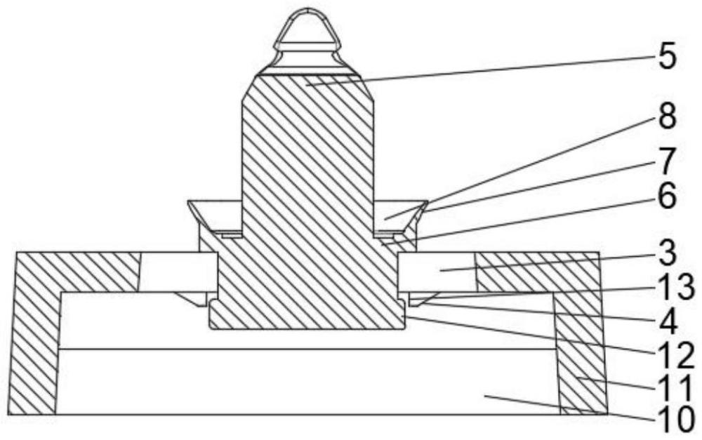
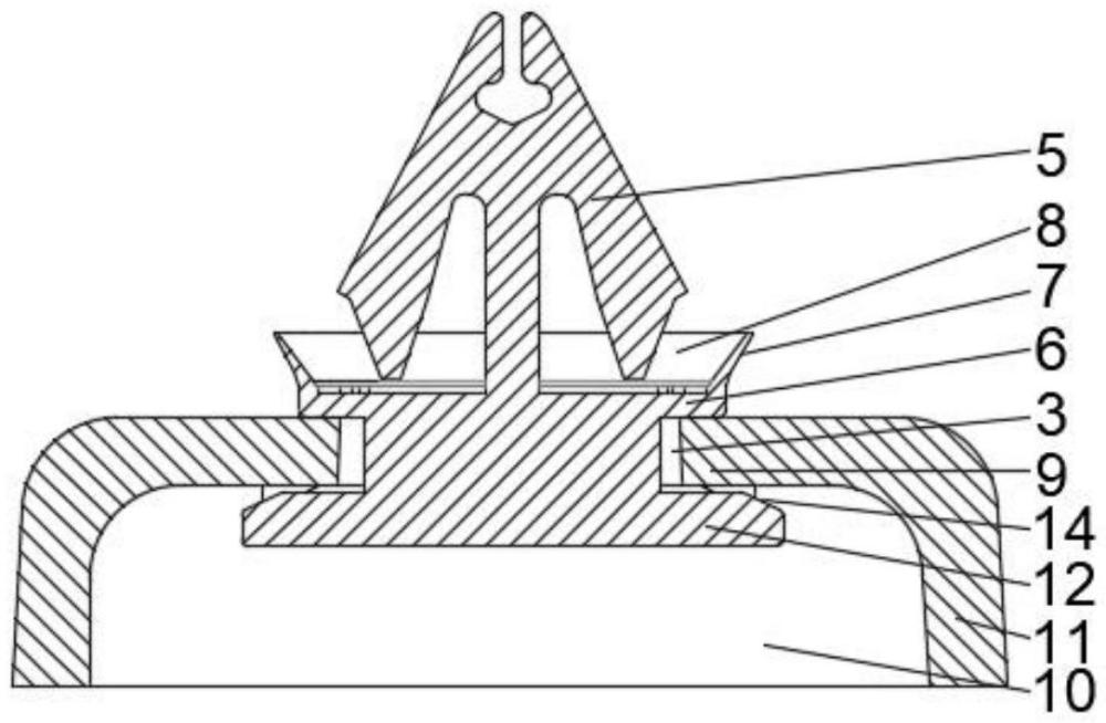
Figures 1~6 are structural schematic diagrams of this utility model. As shown, the rotary snap-fit assembly in this embodiment includes a card holder 1 and a clip 2. The holder 1 is provided with an inlet port 3, whose peripheral edge is seamlessly forming a retaining edge, and the latch 2 has a limiting end; Obstacles are arranged around the inlet 3 of the block 1, which has a guide surface 4 facing the inlet 3; During use, the clip 2 extends into the holder 1 through the inlet 3 via the limiting end, and by rotating, the limiting end passes through the guiding surface 4 and is restricted by an obstacle to the holder 1. This solution improves the fit between the holder 1 and clip 2. By using the flange of the inlet port 3, the clip 2 is limited around the bracket 1, so that after being confined to the holder 1, the clip 2 will not detach from the insertion port 3 in the circumferential direction. By installing obstacles, the limiting end of clip 2 passes through the guide surface 4 and is restricted to the bracket 1. In this state, the clamp 2's assembly direction limits the clip 2, preventing it from swinging or rotating, thereby fixing the bracket 1 and clip 2. In this solution, the assembly process of Clip 2 and Holder 1 is optimized from plug-in fitting to rotational fit, which does not damage the structure of Clip 2 and Holder 1, and is easy to assemble. At the same time, the fit accuracy between Clip 2 and Holder 1 is reduced, eliminating strict dimensional limitations, thereby effectively controlling product quality and yield.
In this embodiment, as shown in Figures 1, 4, and 5, the latch 2 also has a snapping end. When in use, the clamping base 1 is fixed to the preset component, and the latch 2 is assembled on the clamping base 1. The locking end is used to snap and assemble another preset component onto latch 2, completing the assembly of the two preset components. The latch end can be selected with any type of locking limiting structure, such as cantilever, hook, tapered, or tower type, to achieve the purpose of clamping the corresponding component for the snap-on assembly. This will not be repeated here. The locking end of this solution is a tapered clip 5, A limit plate 6 is arranged at the bottom of the tapered clip 5, and the edge of the limit plate 6 gradually extends toward the top end of the conical clip 5, forming a limit skirt 7. Between the limit skirt 7 and the top surface of the limit plate 6 is formed a support cavity 8. The support cavity 8 is conical with a larger upper end and a smaller bottom. During use, the preset component assembled on the latch 2 is restricted by the conical clip 5, forming support for the preset component, resulting in better structural reliability. The limiting end is connected to the bottom of the latch end, specifically located at the bottom of the limit plate 6.
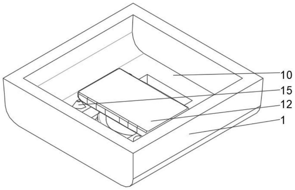
In this embodiment, as shown in Figures 1, 4, and 5, the holder 1 includes a mounting plate 9, which also includes a clearance chamber 10 located inside the mounting plate 9. The inlet port 3 penetrates the surface of the mounting plate 9 and communicates with the clearance chamber 10; Specifically, an inlet 3 is provided on the mounting plate 9, and the bottom of the mounting plate 9 is sealed around several baffles 11. The baffles 11 and the mounting plate 9 form a clearance cavity 10 with an open bottom. During use, the baffles 11 are set on preset components; The clearance cavity 10 is used to provide rotational space for the limit end to improve assembly efficiency and reduce contact friction, making installation smoother and more convenient, and effectively controlling both product quality and yield.
In this embodiment, as shown in Figures 4 and 5, the limiting end has relative upper and lower limiting surfaces. After the limiting end extends into the inlet port 3, the upper surface is located on the outer end face of the inlet port 3, and the lower limiting surface is located on the inner end surface of the inlet port 3; Those close to the recession 10 are inner, while those close to the recession 10 are outside, which will not be repeated here. Rotate the clip 2, and through the limiting surface and lower limiting surface, arrange the limiting end in a clamping manner on the holder 1. In this solution, the cross-section of the limiting end is shaped like the character "工" (工) (工) (工), the bottom surface of the upper flange plate in the "工" shape is the upper limit surface, and the top surface of the lower flange plate in the "工" shape is the lower limit surface (Gong). During use, the "工" opening clamps the bracket 1. This makes the overall rotation buckle 2 more reliable and stable in the limiting position. Of course, the cross-section of the limiting end can also be "Z" or "匚" shape, with a relative upper and lower limit plane structure, which will not be repeated here.
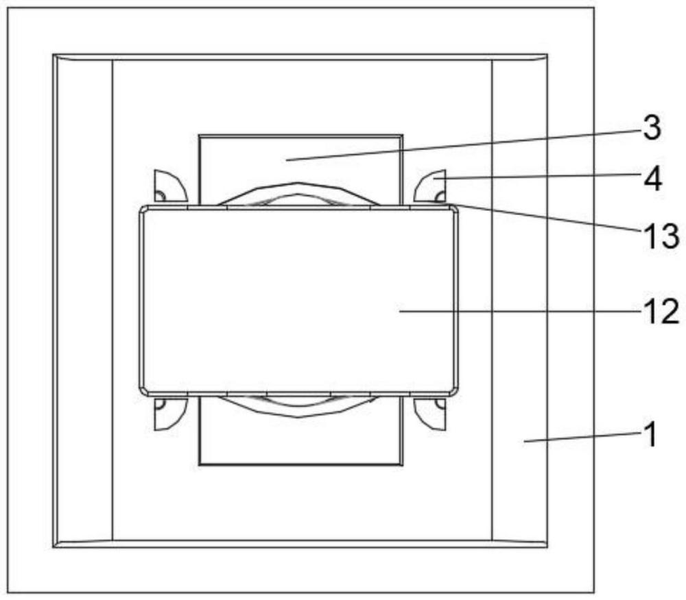
In this embodiment, as shown in Figures 1~6, the inlet 3 has long and short sides of varying lengths and sizes; In this solution, the inlet 3 is rectangular with long and short sides. In practical applications, it can be elliptical or irregular with long and short sides, and other hole-type structures will not be repeated here. The length of the "G"-shaped lower flange plate 12 is between the length and short side dimensions of the inlet 3, and the width of the "G"-shaped lower flange plate 12 does not exceed the short side dimension of the inlet 3; In this solution, the "I"-shaped lower flange plate 12 is conformant to the inlet 3, with the top surface of the lower flange plate 12 serving as the lower limiting surface. The edge size of the lower flange plate 12 is smaller than the edge size of the inlet 3. The specific "I"-shaped lower flange plate 12 is smaller than the edge size of the inlet 3 by 3mm, so that during use, the limit end of the lower flange plate 12 can effectively extend into the inlet 3, with larger assembly tolerance dimensions, reducing manufacturing difficulty and improving assembly efficiency and effectiveness; The length of the "工"-shaped upper flange plate exceeds the short side dimension of the inlet 3; The upper flange plate mainly serves to clamp the limit, only ensuring it exceeds the short side dimension of the inlet 3. Specifically, the "工"-shaped upper flange plate is the limit plate 6 with an elliptical cross-section. The oval long axis and short axis dimensions are both larger than the short side dimensions of the inlet port 3, so that only the lower flange plate 12 in the latch 2 can extend into the inlet 3. The elliptical long axis is parallel to the long side of the lower flange plate 12, and the short axis of the elliptical short axis is parallel to the short side of the lower flange plate 12.
During the driving rotation of the lower flange plate 12 inside the clearance chamber 10, the upper flange plate continuously supports the top surface of the mounting plate 9, serves as a guiding function, prevents the limit end from being trapped in the inlet 3 problem, improves the assembly reliability of the latch 2 and holder 1, and reduces assembly difficulty; The top surface of the limit plate 6 serves as the bottom of the top support chamber 8, and the bottom surface of the limit plate 6 serves as the upper surface of the upper positioning surface, making the overall structure more compact and the connection more reliable; During use, the lower flange plate 12 of the limit end extends into the inlet port 3, and the upper flange plate is supported by the outer end face of the inlet port 3. After the latch 2 is driven to rotate, it clamps the clamping seat 1 through the opening of the '工' character at the limit end.
In this embodiment, the web connecting the upper and lower flange plates of the character "工" (工) is cylindrical. The diameter of the cylindrical web is close to the short side size of the inlet 3 but not exceeding the short side dimension, thereby enhancing structural strength; Among them, the upper and lower limit surfaces are slightly larger than the thickness of the mounting plate 9. Generally, this size is controlled within 3mm per side, specifically 2mm, to meet the requirements for limiting functions as well as convenient and effective assembly, so they will not be repeated here.
In this embodiment, the limiting end and the lock-up end are integrally molded to enhance structural reliability.
In this embodiment, as shown in Figures 2, 5, and 6, the root of the obstacle is set on holder 1, and the head of the obstacle protrudes from holder 1; The guiding surface 4 includes a curved or inclined surface formed by the root of the obstacle converging inward toward the head. The obstacle is used to guide the limit end to rotate toward a preset position and to limit the limit end to the set position of holder 1. The guiding surface 4 further improves the smoothness of the limit end turning over the obstacle and prevents rotation from getting stuck. The guide surface 4 can be spherical, curved, or sloped, etc., and will not be repeated here.
In this embodiment, as shown in Figures 2, 5, and 6, the obstacle also has a check surface 13 at an angle to the guiding surface 4. The check surface 13 is located behind the guide surface 4 in the direction of rotation of the limit end. The position where the limit end contacts the obstacle first is considered front, and the one that contacts the rear is later, which will not be repeated here; After passing through the guide surface 4, the limit end is limited by the obstacle's stop surface 13. The stop surface 13 is used to enhance the limiting capability of the limiting end, reduce the activity of the clip 2 on the bracket 1, and improve structural stability.
In this embodiment, as shown in Figures 2, 5, and 6, the obstacle is formed by the bottom surface of the mounting plate 9 protruding downward; Of course, in practical application, obstacles can also be formed by protruding upward from the top of the mounting plate 9, or the obstacles may be set on both the top and bottom surfaces of the mounting plate 9, and should serve to limit the corresponding upper or lower flange plates 12, so they will not be elaborated here.
As shown in Figure 4, the lower flange plate 12 has a transition surface 14 located at its upper edge; During use, the transition surface 14 passes through the guide surface 4, and the lower flange plate 12 is restricted by obstacles. The transition surface 14 is an inclined surface located on the short side of the lower flange plate 12. The inclined surface slopes outward from top to bottom, and both short sides of the lower flange plate 12 have transition surfaces 14, which further improves the smoothness of the lower flange plate 12 when rotating through the guide surface 4, reduces driving force, improves assembly convenience and efficiency, and also achieves damage-free assembly of the latch 2 and holder 1.
In this embodiment, as shown in Figures 2, 5, and 6, the obstacle includes at least a pair of opposing limit protrusions 15, each of which has a guide surface 4 facing the inlet 3; The side of a pair of limit protrusions 15 opposite the bottom surface of the mounting plate 9 forms a limiting groove for limiting the lower flange plate 12.
Specifically, the obstacle includes two pairs of opposite positioning protrusions 15, each pair of limiting protrusions 15 arranged opposite the long side of the inlet 3 on the corresponding side; Each limit protrusion 15 is 1/4 hemispherical; the hemispherical surface is the guiding surface 4, and the surface of the long side of the hemispherical vertical inlet 3 is the end surface 13; There are four limit protrusions 15 in total, arranged at four corners facing the inlet port 3. Each hemispherical ball face corresponds to the corner facing the inlet port 3; The straight surface facing each other of the pair of limit protrusions 15 is the stop surface 13. The pair of limit protrusions 15 facing each other forms a limit groove 13 with the bottom surface of the mounting plate 9 for limiting the lower flange plate 12. The end face of the limit groove along the long side of the inlet port 3 is U-shaped, with the slot opening facing downward and its side wall perpendicular to the long side of the inlet port 3. The size of the two opposite stop surfaces 13 is slightly larger than the short side of the lower flange plate 12. Generally, one side of this size is controlled within 3mm, specifically 2mm. It is preferable to meet the requirements for limiting functions and convenient and effective assembly, which will not be repeated here; After the obstacle restricts the lower foil plate 12, the two pairs of limit protrusions 15 correspond to both ends of the long side of the lower flange plate 12, and each pair of limit protrusions 15 clamps the lower flange plate 12 in a clamping manner.
In this solution, the obstacle includes two pairs of limit protrusions 15, allowing the lower flange plate 12 to rotate in either direction inside the clearance chamber 10 through the corresponding guide surfaces 4 to the limit grooves formed by the two stop surfaces 13 and the bottom surface of the mounting plate 9. During guidance, the transition surfaces 14 at both ends of the long side of the lower flange plate 12 are guided, improving rotational smoothness. After the lower flange plate 12 rotates, it can be stably restricted to the mounting plate 9 through the limit slots, avoiding the risk of rotation detachment and improving structural reliability.
In this embodiment, as shown in Figure 6, the bottom surface of the limit protrusion 15 is flat, and the guiding surface 4 and the check surface 13 of the limit protrusion 15 transition through this plane. This plane is used to enhance the support and limiting capacity of the limit protrusion 15 on the lower flange plate 12, preventing reverse detachment during rotation and improving the convenience and safety of rotational operation.
Finally, it should be noted that the above embodiments are only intended to illustrate the technical solutions of the present utility model and not to limit them. Although the utility model has been described in detail with reference to preferred embodiments, those skilled in the art should understand that modifications or equivalent substitutions of the technical solutions of this utility model can be made without departing from the purpose and scope of the technical solutions of this utility model, and all such actions should be included within the scope of the claims of the present utility model.






 400-4929-0909
 contact@catarc.com.cn

