The specific embodiment
The technical solution in the embodiment of the present application will be clearly and completely described below in conjunction with the accompanying drawings in the embodiments of the present application, and it is obvious that the described embodiments are only part of the embodiments of the present application, not all embodiments. Based on the embodiments in the present application, all other embodiments obtained by a person skilled in the art without creative work fall within the scope of protection of the present application.
The terms "first", "second", "third" in the present application are for descriptive purposes only and should not be construed as indicating or implying relative importance or implying the number of technical features indicated. Thus, defining the "first", "second", and "third" features may explicitly or implicitly include at least one of these features. In the description of this application, "plurality" means at least two, such as two, three, etc., unless otherwise expressly and specifically qualified. All directional indications (such as up, down, left, right, front, rear...... in the embodiment of the present application ) is only used to explain the relative position relationship between the parts under a specific attitude (as shown in the attached drawing), the movement, etc., and if the specific attitude changes, the directional indication will change accordingly. In addition, the terms "including" and "having" and any variation of them, are intended to cover non-exclusive inclusions. For example, a process, method, system, product, or apparatus that contains a series of steps or elements is not limited to a listed procedure or unit, but may optionally include a step or unit that is not listed, or may optionally include other steps or elements that are inherent to those processes, methods, products, or equipment.
A reference to "embodiment" in this document means that a particular feature, structure or characteristic described in conjunction with an embodiment may be included in at least one embodiment of the present application. The occurrence of the phrase in various places in the description does not necessarily refer to the same embodiment, nor is it an independent or alternative embodiment that is mutually exclusive with other embodiments. It is understood explicitly and implicitly by those skilled in the art that the embodiments described herein may be combined with other embodiments.
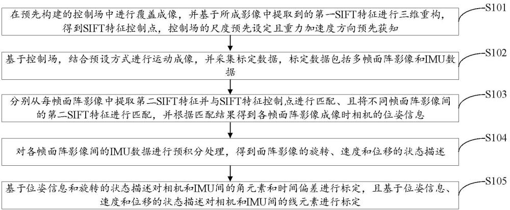
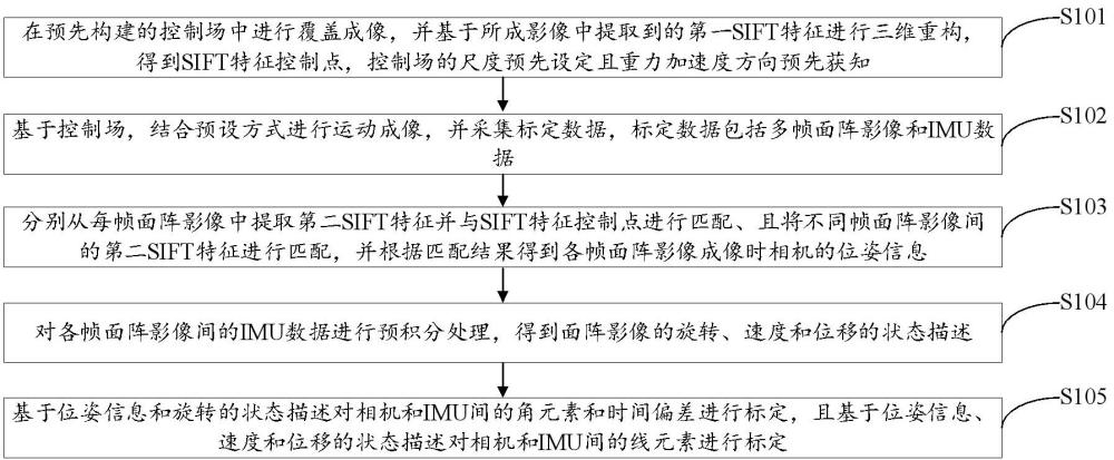
Fig. 1 is a schematic diagram of the flow of the airborne area array camera spatiotemporal calibration method of the embodiment of the present invention. It should be noted that if there is substantially the same result, the method of the present invention is not limited to the sequence of processes shown in Figure 1. As shown in Figure 1, the spatiotemporal calibration method of the airborne area scan camera comprises steps:
Step S101: carrying out coverage imaging in a pre-constructed control field, and performing three-dimensional reconstruction based on the first SIFT feature extracted from the finished image, obtaining a SIFT feature control point, the scale of the control field is preset and the direction of gravitational acceleration is known in advance.
It should be noted that the control field is a guarantee system for camera positioning and orientation. In order to achieve this purpose, it should have the following characteristics: in order to ensure the imaging clarity, the imaging distance (i.e., the average distance from the camera's imaging position to the control field) should generally be greater than 30 meters, and the ratio of the depth of the control scene to the imaging distance should be greater than 1/ 30. The ratio of the control field range to the imaging range of the mainstream camera is greater than 2; the control field needs to be equipped with a control point mark, which can be accurately measured by the total station, and can also accurately obtain the position on the imaging image; ensure that at least 8 control signs can be imaged when the mainstream camera imaging, and be evenly distributed on the image. After the control field is laid out, a high-precision total station is set up at the appropriate position, and the coordinates of all control points in the control field are accurately measured after leveling, and the obtained coordinate scale is obviously 1 and the gravity direction is known.
In this embodiment, the SIFT feature control field construction is realized through a three-dimensional reconstruction technique (Structure from motion, SFM). Specifically, the step S101 specifically comprises the following steps:
1. The high-resolution fixed-focus camera is used to cover the control field to obtain the control field image.
Specifically, when carrying out coverage imaging, firstly, three imaging stations are selected, and the distance between the stations is greater than 5 meters, so that the control field can be clearly imaged; then, at one of the imaging stations, the handheld camera uses the imitation route method to image the control field, and the overlap degree of images in and between the flight bands is guaranteed to be greater than 50%, and all images can cover the entire inspection field, and the process is repeated to complete the imaging of the three imaging stations.
2. The coordinates of the control point in the control field obtained in advance are associated with the coordinates of the imaging point corresponding to the control point on the control field image.
3. Based on the correlation between the coordinates of the control point and the coordinates of the imaging point, the initial external orientation element of the camera is obtained by using the initial internal parameters of the camera.
Specifically, the correlation between the coordinates of the control point and the coordinates of the imaging point is used to perform a direct linear transformation (such as the kneip-P3P method) based on the initial internal parameters of the camera to obtain the initial external orientation element of the camera (i.e., the position and attitude of the camera in the calibration field).
4. Extract the first SIFT feature from each control field image separately.
Specifically, the first SIFT feature and its corresponding descriptor are extracted from the control field image.
5. Match the first SIFT features between different control field images, and retain the control field image pairs whose number of associated feature points meets the preset number threshold after matching.
Specifically, the descriptor is used to realize the first SIFT feature matching of different control field images, and the basic matrix constructed by the initial external orientation element is used to filter the error matching, and the number of associated feature points after matching meets the preset number threshold of the control field image pairs is retained, and the preset number threshold is preferably set to 8.
6. The SIFT feature control points were obtained by 3D reconstruction based on the associated feature points that were successfully matched in the initial external azimuth element, the initial internal parameters of the camera and the control field image pair.
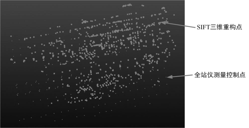
Specifically, triangulation is carried out firstly, that is, the initial three-dimensional coordinates are estimated based on the associated feature points that are successfully matched by the initial external azimuth element and the initial internal reference pair of the camera. Then, the beam adjustment without camera internal control and the beam adjustment with camera internal parameters were carried out, respectively, the initial external azimuth element and the initial 3D coordinate were optimized by the optimization method, the control point constraint and the SIFT feature association constraint, and the beam adjustment with camera internal control was optimized by the optimization method, the control point constraint and the SIFT feature association constraint. Secondly, the aerotriangulation quality assessment is carried out, that is, whether there are abnormal associated feature points (such as the point where the triangulation angle is too small, the point with large projection error) and the point error with a large puncture point in the adjustment results; if not, the data is considered to be qualified, otherwise it is necessary to adjust and re-perform the beam adjustment without camera internal control and the beam adjustment with camera internal control. Finally, the SIFT feature control points are output, and if there is no abnormality in the aerotriangulation quality assessment, the SIFT 3D reconstruction point coordinates and their descriptors are exported as SIFT feature control points, and the typical reconstruction results are shown in Figure 2.
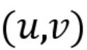
It should be noted that, theoretically, the pixel coordinates![]() of a point
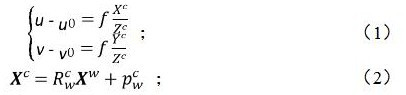
![]() (control point or SIFT feature reconstruction point) in the calibration field on the image plane can be expressed as:
![]()
Among them,![]() it is the coordinate of the control field midpoint
![]() in the image space coordinate system,
![]()
![]() the rotation and translation from the camera coordinate system to the inspection field coordinate system, and the
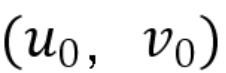
![]() camera focal length and
![]() the camera principal point. From the equation (1)~(2), the residual formula between a point in the calibration field and the imaging pixel can be constructed, so as to realize the beam adjustment in the above steps, and obtain the exact value of the coordinate value of each SIFT feature control point in the control field coordinate system.
Step S102: based on the control field, combined with the preset mode for motion imaging, and collecting calibration data, the calibration data comprises multi-frame area array images and IMU data.
Specifically, after the large-scale control field is constructed in advance, motion imaging is carried out based on the control field and combined with the preset mode, and the calibration data includes multi-frame area array images and IMU data.
It should be noted that the existing ground calibration scheme is mainly used for the external azimuth element of Visual-inertialodometry (VIO) and IMU initialization calibration, and is suitable for high-frequency triggering cameras (above 10Hz), so there is the assumption that the IMU angular velocity deviation and acceleration deviation remain unchanged at different times during the calibration period, which is not consistent with the performance of commonly used aerial cameras (generally the trigger frequency is less than 1Hz), and the relevant assumptions cannot be used. Therefore, the present embodiment completes the acquisition of synchronous calibration data between the camera and the IMU through "static-dynamic-static", which not only ensures that the velocity at the initial moment and the end moment is zero, but also makes the IMU angular velocity deviation at the initial moment and the end moment can be directly read through the IMU data, so as to increase the reliability of the estimation results by using these constraints. Specifically, the step S102 specifically comprises the following steps:
1. Under the condition that the heading of the payload equipment is facing the sky direction and the imaging direction is facing the control field, the payload equipment is placed in the initial static state, and at least the first preset number of area array images are collected and the IMU data is collected at the same time.
Specifically, the present embodiment may carry out data acquisition according to a handheld device such as the weight of the equipment or placed on a motion platform, and the load heading direction is toward the zenith direction and the imaging direction is towards the control field when the data is collected, and then the load equipment is placed in an initial static state, and at least the first preset number of area array images are collected and IMU data is collected simultaneously, and the first preset number is preferably set to at least 2 groups.
2. The control load equipment rotates clockwise and counterclockwise around its own X, Y, and Z axes respectively, and collects a second preset number of area array images and collects IMU data at the same time when rotating around each axis.
Specifically, the control load equipment rotates clockwise and counterclockwise around its own X, Y, and Z axes respectively, with a rotation angle greater than 20 degrees, and each axis collects at least a second preset number of area array images and IMU data, and the second preset number is preferably set to 10 groups.
3. Put the load equipment in the end static state, collect at least the first preset number of area array images, and collect IMU data at the same time.
In this embodiment, the spatiotemporal calibration is completed by constructing the pre-constraints (the angular velocity deviation of the IMU at the initial moment and the end time is known, and the velocity at the initial time and the end time is 0) through the "static-dynamic-static" data acquisition mode, and the direction and magnitude of the apparent gravitational acceleration are known, and these more accurate assumptions will improve the calibration accuracy and make the final calibration results more accurate.
step S103: extracting a second SIFT feature from each frame area array image and matching it with the SIFT feature control point, matching the second SIFT feature between different frame area array images, and obtaining the pose information of the camera when each frame area array image is imaged according to the matching result.
Specifically, after obtaining the area array images, the second SIFT feature is extracted from all the area array images, and then the second SIFT feature is matched with the SIFT feature control point, and the second SIFT feature of the area array images of different frames is matched, and finally the pose information of the camera during the imaging of the area array image of each frame is obtained by combining the matching results.
Further, step S103 specifically comprises the following steps:
1. Extract the second SIFT feature from each frame of area array image.
2. Match the second SIFT feature with the SIFT feature control point to confirm the orientation element outside the image.
Specifically, the second SIFT feature is matched with the SIFT feature control point, and the external orientation elements of the image are confirmed by kneip-P3P+RANSAC (Random Sample Consensus).
3. The second SIFT features between different frame area array images are matched, and the matching feature points are filtered by using the initial external orientation element to obtain the matching feature points.
4. According to the pixel displacement of the matching feature points between the area array images, confirm the static area array images in the initial static state and the end static state.
Specifically, according to the pixel displacement of the matching feature points between the area array images (i.e., the parallax of each matching feature point), the area array images in the initial static state and the end static state are judged, and part of the static area array images are eliminated, so that two static area array images are retained in the initial stage and the end stage.
5. Based on the beam adjustment, the pose estimation of the non-static area array image is carried out, and finally the pose information of the camera during the imaging of each frame area array image is obtained.
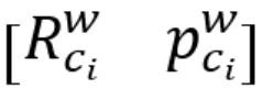
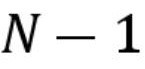
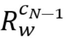
Specifically, the image pose data is used as the input data for spatiotemporal calibration, wherein the pose of the first![]() frame image is:
![]() , where , is
![]() the rotation parameter and position parameter of the camera in the control field coordinate system when the
![]() first
![]() frame image is imaging.
Step S104: perform pre-integration processing on the IMU data between the area array images of each frame to obtain the state description of the rotation, velocity and displacement of the IMU.
It should be noted that, in principle, given the initial pose and velocity, the IMU pose can be obtained by the integral of the angular velocity![]() and acceleration value
![]() obtained by the IMU measurement, but the measured value not only includes Gaussian white noise and wandering deviation, and the acceleration measurement value should subtract the influence of gravitational acceleration
![]() . From this, the IMU measurement model can be described as:
![]()
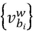
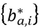
where and![]()
![]() are the angular velocity and linear acceleration values of the IMU in the global frame, the
![]() rotation matrix of the IMU in the world coordinate system, and the
![]() Gaussian white noise and wander deviation of
![]() the angular velocity,
![]() and
![]() the Gaussian white noise and wander deviation of the linear acceleration values, respectively. In this embodiment, the IMU data between camera frames is preprocessed by pre-integral, and the corresponding IMU data between adjacent frames of a continuous camera is the first
![]() to the first
![]() moment, then the rotation, velocity and displacement of the IMU pre-integration can be described as:
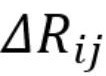
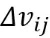
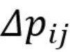
![]()
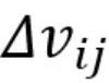
Wherein,![]() the rotation difference from the first
![]() to the first
![]() time, the
![]() velocity difference from the first
![]() to the first
![]() time,
![]() the displacement difference from the first
![]() to the first
![]() time, the
![]() time between the first and the first
![]() time, and
![]()
![]() the time difference between the first
![]() and first
![]() moments.
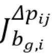
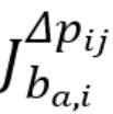
If the angular velocity deviation and acceleration deviation![]()
![]() in the pre-integration are taken into account, the IMU integration acquisition status is:
![]()
Wherein:![]() is the rotation matrix and translation vector of the IMU in the world coordinate system at the first
![]() time,
![]()
![]() the rotation matrix and translation vector of the IMU in the world coordinate system at the first
![]() time,
![]() and the velocity of the IMU in the world coordinate system at the first
![]()
![]() time,
![]() and
![]() the
![]() time difference at the first
![]() time;
![]()
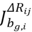
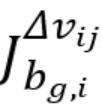
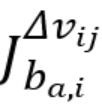
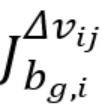
![]() is the derivative of the rotation preintegration pair
![]() ,
![]() is
![]() the velocity
![]()
![]() preintegration pair
![]() ,
![]() is the derivative of the displacement preintegration pair
![]() ,
![]() and the above derivatives can be obtained from the preintegration process.
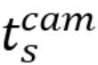
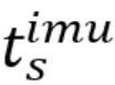
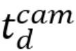
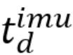
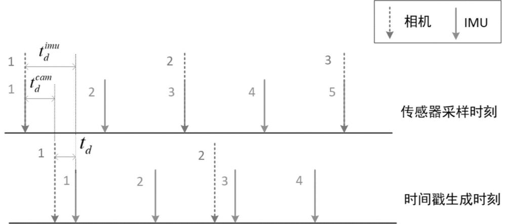
Further, as shown in Figure 3, there is a misalignment between the sensor sampling time and the measurement time due to clock out-of-sync, propagation delays, sensor responses, and operating system overhead. If the camera and IMU data are sampled at the![]() same time, the actual timestamps of the camera and IMU measurements are:
![]()
where , , is the![]()
![]() actual timestamp of the camera and IMU,
![]() and is
![]() the time-lapse of the camera and IMU, respectively. This defines the time offset
![]() between the camera and the IMU:
![]()
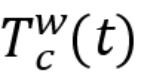
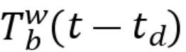
From this, it can be obtained that there is the following relationship between the pose between the camera and the IMU:
![]()
wherein,![]() is the
![]() camera pose at the sampling time,
![]()
![]() the IMU at the sampling time, and
![]() the camera pose in the IMU coordinate system. Obviously, the so-called spatiotemporal calibration is the process of estimating the time offset
![]() and the relative transformation matrix
![]() between the camera and the IMU (including angular elements
![]() and line elements
![]() ). Therefore, step S104 specifically comprises the following steps:
1. Build the time offset to build the spatio-temporal synchronization state between the camera and the IMU.
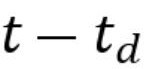
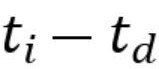
Specifically, the present invention![]() linearly interpolates the rotation matrix and the translation vector of the IMU at the moment in the world coordinate system as follows:
![]()
wherein, is![]() the
![]() angular velocity of the IMU in the body coordinate system at the time, and
![]()
![]() the linear velocity of the IMU in the world coordinate system at the time. From this, the spatiotemporal synchronization status of the camera and the IMU can be described as:
![]()
2. Based on the spatio-temporal synchronization state, the IMU data between each frame of area array images are pre-integrated to obtain the state description of the rotation, velocity and displacement of area array images.
Specifically, the rotation, velocity, and displacement states of the area array image are described as follows:
![]() ;(13)
![]() ;(14)
![]() ;(15)
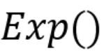
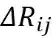
Wherein,![]() it represents the rotation preintegration of the camera in the control field coordinate system when the first
![]() frame image is imaging, represents
![]() the rotation preintegration of the camera in the control field coordinate system when the first
![]() frame image is imaging,
![]() represents the angular element,
![]() represents the exponential function, and
![]() represents
![]() the angular velocity
![]()
![]() of the IMU in the body coordinate system at the momentThe angular velocity of the IMU in the body coordinate system at the moment represents the
![]() time offset between the camera and the IMU,
![]() the rotation difference from the first
![]() to the first
![]() moment,
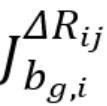
![]() the derivative of the rotation preintegration pair
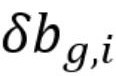
![]() , the
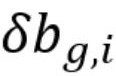
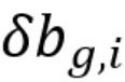
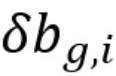
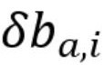
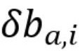
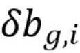
![]() angular velocity deviation, and
![]() the velocity preintegration of
![]()
![]() the IMU in the world coordinate system at the first
![]() timeThe velocity preintegration of the IMU at the moment in the world coordinate system represents the
![]() acceleration of gravity, the
![]() time difference between the first
![]() and first
![]() moments,
![]() the velocity difference between the first
![]() and first
![]() moments,
![]() the derivative of the velocity preintegration pair
![]() , and
![]() the derivative
![]() of the velocity preintegration pair
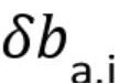
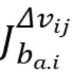
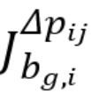
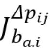
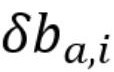
![]() Represents the acceleration deviation,
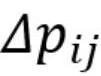
![]() represents the displacement preintegration of the camera in the control field coordinate system when the first
![]() frame image is imaging, represents
![]() the displacement preintegration of the camera in the control field coordinate system during the first
![]() frame image imaging,
![]() represents the displacement difference from the first
![]() to the first
![]() time,
![]() represents the derivative of the displacement preintegration pair
![]() , and
![]() represents the displacement preintegration pair
![]() , which represents the
![]() line element.
Step S105: calibrating the angular elements and time deviations between the camera and the IMU based on the pose information and the state description of rotation, and calibrating the line elements between the camera and the IMU based on the state descriptions of the pose information, velocity and displacement.
Specifically, after obtaining the pose information, the angular element and time deviation between the camera and the IMU can be calibrated by using the pose information and the rotation prediction component, and the line element between the camera and the IMU can be calibrated by using the pose information, velocity preintegration and displacement preintegration.
Further, the steps to calibrate the angular element and time deviation between the camera and the IMU based on the pose information and the state description of the rotation include:
1. Construct the residual formula based on the state description of rotation.
Specifically, because the time difference between the continuous images to be processed in this embodiment is large, it is assumed that the angular velocity deviation of the IMU at different times is different. In the present embodiment, the residuals are constructed through equation (13) to achieve calibration. In Eq. (13), the rotation matrix can be expressed based on quaternions as:
![]()
where is the![]() quaternion representation of the lower corner element of the camera in the IMU coordinate system, and
![]()
![]() the conjugate quaternion represents
![]() the inverse transformation.
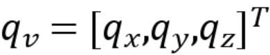
Quaternions![]() can be defined as:
![]()
Among them,![]() they are the real part of the quaternion, the
![]() imaginary part of the direction, the
![]() imaginary part of the direction, and
![]() the imaginary part of the direction.
![]()
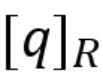
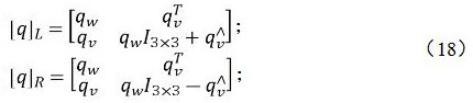
Then the quaternion left-multiplication![]() and right-multiplication operations
![]() can be defined as:
![]()
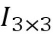
Among them![]() is the vector-oriented
![]() antisymmetry matrix,
![]() which represents the diagonal matrix of units of 3×3 size.
2. Initialize the angular velocity deviation at different moments.
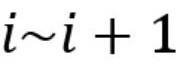
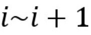
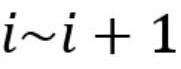
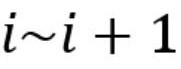
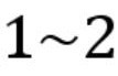
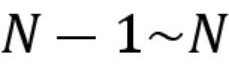
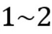
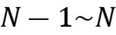
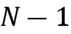
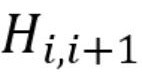
Specifically, in the data collected in this embodiment, the first![]() frame area array image and the first
![]() frame area array image are static, so the true value of the IMU angular velocity during this period is 0, and the measured value can be known to be the sum of the angular velocity wandering deviation
![]() and the measured noise
![]() according to the IMU measurement model (see equation (3)),
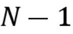
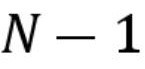
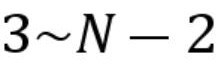
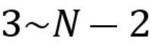
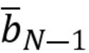
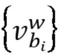
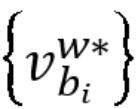
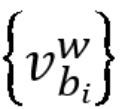
![]() and the 5 frames of IMU angular velocity data adjacent to the second frame area array image between the first
![]() frame area array images are takenThe angular velocity data of the 5 frames of IMU adjacent to the first
![]() frame of the area array images between the frame area array images are taken as the average
![]() value and
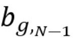
![]() the angular velocity deviation of the IMU at the second and second moments,
![]() and the first
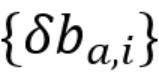
![]() is obtained by linear interpolationThe initial value of the angular velocity deviation of the IMU at the moment is used to pre-integrate the IMU data between image frames. It needs to be understood that, in the existing scheme, the camera frequency adopted is high, so the deviation of the camera at different moments can be identified as the same, but, in the present invention, the camera adopted is no longer limited to the high-frequency camera, and the low-frequency camera can also be adopted, and the low-frequency camera cannot simply identify the deviation of different moments is the same, therefore, the present invention utilizes the static data of the initial and end moments to initialize the gravitational acceleration deviation at different moments.
3. Based on the angular velocity deviation at different moments, the residual formula is used to calibrate the angular element, the time deviation and the angular velocity deviation at different times.
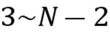
Specifically, for the calibration of the angular elements![]() , the equation of data existence between the first surface array images can be obtained
![]() by shifting the term in equation (16):
![]()
Under the![]() conditions, the estimation using the least squares pairs
![]() :
![]()
![]()
![]() , is the conjugate quaternion representation of the lower corner elements of the camera in the IMU coordinate system, which is converted into a rotation matrix
![]() to complete the calibration.
For the calibration of the time deviation![]() , the equation between the data between the first area array images can be obtained
![]() by shifting the term of equation (16):
![]()
If it is ordered![]() , then the imaginary part of the quaternion in equation (21) can be arranged:
![]()
The time deviation![]() is calibrated using the least squares method:
![]() ;(23)
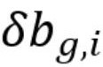
Calibration: Calibration for angular velocity deviation![]() at different moments:
The equation of data existence between the first area array images can be obtained![]() by shifting the term in equation (16):
![]()
If ordered:
![]() ;
Rule:
![]()
Using the least squares, the correction of the angular velocity deviation of the IMU at the first![]() moment is as follows:
![]()
In this way, the angular velocity deviation at the first![]() moment is corrected, so that the angular velocity deviation at different moments can be calibrated.
3. Judge whether the time deviation exceeds the preset time deviation threshold.
Specifically, this preset time deviation threshold is preset.
4. If it is not exceeded, confirm that the angular element, time deviation and angular velocity deviation at different times are calibrated.
5. If it is exceeded, the time deviation obtained by the calibration is recycled to pre-integrate the IMU data again and then calibrated again, and the time deviation in the new calibration result is compared with the preset time deviation threshold again until the time deviation is lower than the preset time deviation threshold. Further, the steps to calibrate the line elements between the camera and the IMU based on the posture information, velocity, and displacement state descriptions include:
1. The IMU data is pre-integrated based on the calibration data after the completion of the calibration of angular elements, time deviations and angular velocity deviations at different moments to obtain new velocity and new displacement state descriptions.
Specifically, before calibrating the line elements, the pre-integration is re-integrated by using the calibrated angular elements, time deviations, and angular velocity deviations at different times, and equations (14) and (15) can be deformed as:
![]()
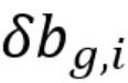
The present embodiment carries out the calibration of the line element based on this formula, in addition to the element, there are unknown gravitational acceleration![]() , acceleration deviation
![]() in the present embodiment, and in the present embodiment, the gravitational direction of the control field is known, and can be described as
![]() , so only the gravitational acceleration norm
![]() is estimated, and the formula (27)~(28) of the first
![]() moment can be expressed as:
![]()
Thereinto:
![]()
![]() 。
2. Initialize the gravitational acceleration deviation at different moments.
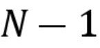
Specifically, in the data collected in this embodiment, the first![]() frame area array image and the first
![]() frame area array image are static, so the true value of IMU acceleration during this period is 0, and the measured value is the sum of acceleration drift deviation
![]() , measurement noise
![]() and gravitational acceleration according to the IMU measurement model (see equation (3)), and the average value of the five IMU acceleration data adjacent to the second frame area array image between the first
![]() area array images is taken
![]()
![]() After the average value
![]() of the 5 frames of IMU acceleration data adjacent to the first
![]() frame area array image between the frame area array images, the gravitational acceleration deviation of the IMU at the second
![]() and time can be calculated:
![]()
Wherein:![]() and
![]() is the transposition of the rotation matrix of the camera in the world coordinate system at the second time,
![]() which
![]() is obtained by calibrating the diagonal element. The initial value of the gravitational acceleration deviation of the IMU at the first
![]() moment is obtained by linear interpolation, and the gravitational acceleration deviation is used to preintegrate the IMU data between the area array image frames. It needs to be understood that, in the existing scheme, the frequency of the camera adopted is high, so the deviation of the camera at different moments can be identified as the same, but, in the present invention, the camera adopted is no longer limited to the high-frequency camera, and the low-frequency camera can also be used, and the low-frequency camera cannot simply identify the deviation of different moments is the same, therefore, the present invention utilizes the static data of the initial and end moments to initialize the gravitational acceleration deviation at different moments.
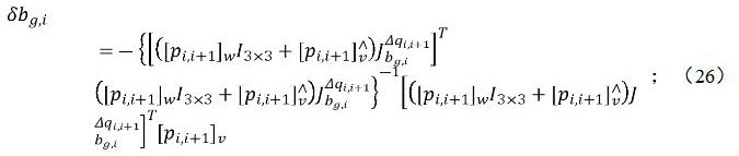
3. When the direction of gravitational acceleration in the control field is known, the line element, gravitational acceleration, velocity and acceleration deviation are calibrated respectively in combination with the direction of gravitational acceleration, the gravitational acceleration deviation at different moments, the new velocity and the state description of the new displacement.
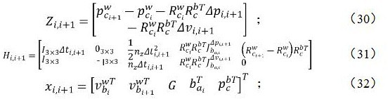
Specifically, calibration is performed for line elements![]() , gravitational acceleration
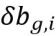
![]() , and velocity
![]() :
After setting the![]() corresponding column to
![]() 0, the least squares method is used to estimate the unknown parameters:
![]()
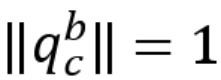
Wherein,![]() the conjugate quaternion representing gravitational acceleration
![]() and
![]() the conjugate quaternion representing velocity
![]() are 0 due to the particularity of the data acquisition in this embodiment, and the corresponding
![]()
![]() column can be set
![]() to 0 in the above optimization.
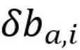
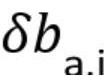
Calibration for acceleration deviation![]() :
After setting the![]() middle, and
![]() corresponding columns to 0,
![]() the least squares method is used to estimate
![]() the unknown parameters:
![]()
Among them,![]() it is expressed.
3. Determine whether the gravitational acceleration exceeds the preset acceleration threshold.
Specifically, this preset acceleration threshold is preset.
4. If it is not exceeded, confirm that the calibration of line elements, gravitational acceleration, velocity and acceleration deviation is completed.
5. If it is exceeded, the acceleration deviation obtained by the calibration is recycled to pre-integrate the IMU data again and then calibrate, and the gravitational acceleration in the new calibration result is compared with the preset acceleration threshold again until the gravitational acceleration is lower than the preset acceleration threshold.
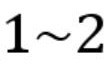
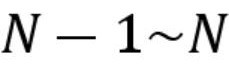
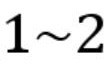
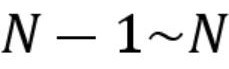
It is understandable that in the existing scheme, the angular velocity deviation and acceleration deviation of the IMU at different times can be considered the same because the high-frequency camera is used for data acquisition. And the present invention adopts a low-frequency camera to collect data, therefore, the angular velocity deviation and acceleration deviation of IMU at different moments can not be directly identified as the same, resulting in the increase of unknowns, and in order to reduce the unknowns in the calibration process, the present invention restricts the data acquisition process when carrying out data acquisition, so that the scale and gravity direction of the SIFT characteristic control field are known, and then the method of solving different values to be estimated in steps realizes the calibration of all worthiness.
The spatiotemporal calibration method of the airborne area array camera in the present embodiment obtains the SIFT feature control point by carrying out coverage imaging in the control field with a preset scale and the direction of gravitational acceleration is known, and then the calibration data is collected in combination with the control field, and the calibration data comprises multiple frames of area array images and IMU data, and then the pose information of the camera when each frame area array image is imaged is extracted from each frame area array image respectively, and then the IMU data between each frame area array image are pre-integrated to obtain the rotation, The state description of velocity and displacement, and finally the angular elements, time deviation and line elements between the camera and the IMU are calibrated based on the posture information and the state description of rotation, velocity and displacement, and based on the pre-constructed large-scale SIFT feature control field, which has the specificity of knowing the direction of gravitational acceleration and the known scale, so as to ensure the clear imaging quality of aerial images, and no longer need to estimate the direction of gravitational acceleration in the calibration process, so as to reduce the number of parameters that need to be estimated in the calibration process, so as to improve the accuracy of calibration.
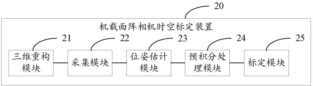
Fig. 4 is a schematic diagram of the functional module of the airborne area array camera spatiotemporal calibration device of the embodiment of the present invention. As shown in Fig. 4, the airborne area array camera spatiotemporal calibration device 20 comprises a three-dimensional reconstruction module 21, an acquisition module 22, a pose estimation module 23, a preintegration processing module 24 and a calibration module 25.
the three-dimensional reconstruction module 21 is used for carrying out coverage imaging in the preconstructed control field, and carrying out three-dimensional reconstruction based on the first SIFT feature extracted from the finished image, obtaining the SIFT feature control point, the scale of the control field is preset and the gravitational acceleration direction is known in advance;
the acquisition module 22 is used for carrying out motion imaging based on the control field, combining with a preset mode, and collecting calibration data, and the calibration data comprises a multi-frame area array image and IMU data;
the pose estimation module 23 is used for extracting a second SIFT feature from each frame area array image and matching it with the SIFT feature control point, and matching the second SIFT feature between different frame area array images, and obtaining the pose information of the camera when each frame area array image is imaged according to the matching result;
the pre-integration processing module 24 is used for pre-integrating the IMU data between each frame area array image to obtain the state description of rotation, velocity and displacement of area array image;
The calibration module 25 is used for calibrating the angular element and the time deviation between the camera and the IMU based on the posture information and the state description of the rotation, and calibrating the line element between the camera and the IMU based on the state description of the pose information, velocity and displacement.
Optionally, the 3D reconstruction module 21 performs an operation of carrying out coverage imaging in a preconstructed control field and performing 3D reconstruction based on the first SIFT feature extracted from the finished image to obtain a SIFT feature control point, comprising:
The high-resolution fixed-focus camera was used to cover the control field to obtain the control field image.
The coordinates of the control points in the pre-obtained control field are associated with the coordinates of the imaging points corresponding to the control points on the control field image.
Based on the correlation between the coordinates of the control point and the coordinates of the imaging point, the initial external azimuth element of the camera is obtained by using the initial internal parameters of the camera.
The first SIFT feature was extracted from each control field image respectively.
The first SIFT features between different control field images are matched, and the number of associated feature points after matching is retained.
The SIFT feature control points were obtained by 3D reconstruction based on the initial external orientation element, the initial internal control of the camera and the successfully matched associated feature points in the control field image pair.
Optionally, the acquisition module 22 performs operations based on the control field, combined with a preset mode for motion imaging, and collects calibration data, comprising:
Under the condition that the heading direction of the payload device is facing the sky direction and the imaging direction is facing the control field, the payload device is placed in the initial static state, and at least the first preset number of area array images are collected and the IMU data is collected at the same time;
the control load equipment rotates clockwise and counterclockwise around its own X, Y, and Z axes respectively, and collects a second preset number of area array images and collects IMU data simultaneously when rotating around each axis;
The payload device is placed in the end static state, and at least the first preset number of area array images are acquired, and the IMU data is collected at the same time.
Optionally, the pose estimation module 23 performs operations that extract the second SIFT feature from each frame area array image and match it with the SIFT feature control point, match the second SIFT feature between different frame area array images, and obtain the pose information of the camera when each frame area array image is imaged according to the matching result, specifically comprising:
The second SIFT feature was extracted from each frame of area array image.
The second SIFT feature is matched with the SIFT feature control point to confirm the orientation element outside the image.
The second SIFT features between different frame area array images are matched, and the matching feature points are filtered by using the initial external orientation element to obtain the matching feature points.
According to the pixel displacement of the matching feature points between the area array images, the static area array images in the initial static state and the end static state are confirmed.
Based on the beam adjustment, the pose estimation of the non-static area array image is carried out, and finally the pose information of the camera during the imaging of each frame of area array image is obtained.
Optionally, the pre-integration processing module 24 performs pre-integration processing on the IMU data between each frame of area array images to obtain the state description of rotation, velocity and displacement of area array images, specifically comprising;
Construct time offset: construct spatiotemporal synchronization state between camera and IMU;
Based on the spatiotemporal synchronization state, the IMU data between the area array images of each frame are pre-integrated to obtain the state description of the rotation, velocity and displacement of the area array images.
Optionally, the calibration module 25 performs operations for calibrating angular elements and temporal deviations between the camera and the IMU based on the pose information and the state description of the rotation, comprising:
The residual formula is constructed based on the state description of rotation.
Initialize angular velocity deviations at different moments;
Based on the angular velocity deviation at different moments, the residual formula is used to calibrate the angular element, the time deviation and the angular velocity deviation at different times.
Determine whether the time deviation exceeds the preset time deviation threshold;
If it is not exceeded, it is confirmed that the angular element, time deviation and angular velocity deviation at different times are calibrated;
If it is exceeded, the IMU data is pre-integrated again by recycling the time deviation obtained from the calibration and then calibrated again, and the time deviation in the new calibration result is compared with the preset time deviation threshold again until the time deviation is lower than the preset time deviation threshold.
Optionally, the calibration module 25 performs the operation of calibrating the line element between the camera and the IMU based on the state description of the pose information, velocity and displacement, comprising:
Based on the calibration data of angular elements, time deviations and angular velocity deviations at different times, the IMU data are pre-integrated to obtain new velocity and new displacement state descriptions.
Initialize the gravitational acceleration deviation at different moments;
When the direction of gravitational acceleration in the control field is known, the line element, gravitational acceleration, velocity and acceleration deviation are calibrated by combining the direction of gravitational acceleration, the gravitational acceleration deviation at different moments, the new velocity and the state description of the new displacement, respectively.
Determine whether the gravitational acceleration exceeds the preset acceleration threshold;
If it is not exceeded, it is confirmed that the calibration of line element, gravitational acceleration, velocity and acceleration deviation is completed;
If it is exceeded, the acceleration deviation obtained by the calibration is recycled to pre-integrate the IMU data and calibrated again, and the gravitational acceleration in the new calibration result is compared with the preset acceleration threshold again until the gravitational acceleration is lower than the preset acceleration threshold.
For other details of the technical scheme for the implementation of each module in the airborne area scan camera spatio-temporal calibration device of the above embodiment, please refer to the description in the spatiotemporal calibration method of the airborne area scan camera in the above embodiment, and will not be repeated here.
It should be noted that each embodiment in this specification is described in a progressive manner, and each embodiment focuses on the differences from other embodiments, and the same and similar parts between each embodiment can refer to each other. For device embodiments, because they are basically similar to the method embodiments, the description is relatively simple, and the relevant places can be described in part of the method embodiments.
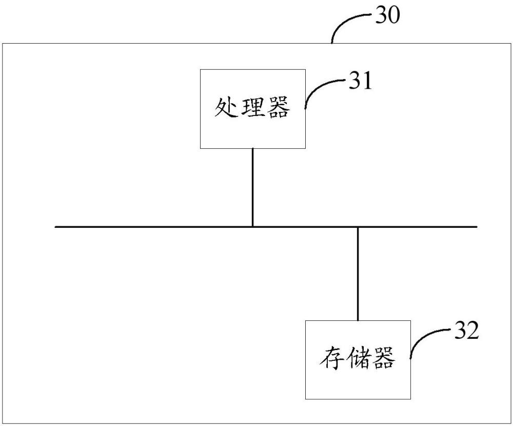
Refer to FIG. 4, FIG. 4 is a schematic diagram of the structure of the computer equipment of the embodiment of the present invention. As shown in Figure 4, the computer device 30 comprises a processor 31 and a memory 32 coupled with the processor 31, a program instruction is stored in the memory 32, and when the program instruction is executed by the processor 31, the processor 31 is made to perform the spatiotemporal calibration method step of the airborne area array camera described in any embodiment.
Wherein, the processor 31 can also be called a resource (Central Processing Unit, central processing unit). The processor 31 may be an integrated circuit chip with the ability to process signals. The processor 31 may also be a general-purpose processor, a digital signal processor (DSP), an application-specific integrated circuit (ASIC), a field-programmable gate array (FPGA) or other programmable logic device, a discrete gate or transistor logic device, or a discrete hardware component. A general-purpose processor can be a microprocessor, or the processor can be any regular processor, etc.
Refer to FIG. 5, FIG. 5 is a schematic diagram of the structure of the storage medium of the embodiment of the present invention. The storage medium of the embodiment of the present invention stores a program instruction 41 that can realize the spatiotemporal calibration method of the airborne area array camera, wherein the program instruction 41 can be stored in the storage medium in the form of a software product, and comprises a plurality of instructions to enable a computer device (which may be a personal computer, a server, or a network device, etc.) or a processor (processor) to perform all or part of the steps of the method described in each embodiment of the present application. The aforementioned storage media include: U disk, mobile hard disk, read-only memory (ROM, Read-Only Memory), random access memory (RAM), disk disks or optical discs and other media that can store program code, or computers, servers, mobile phones, tablets and other computer equipment and equipment.
In several embodiments provided in the present application, it should be understood that the disclosed computer equipment, apparatus and methods may be realized by other means. For example, the device embodiments described above are only schematic, for example, the division of units is only a logical function division, and there can be other ways of division in actual implementation, such as multiple units or components can be combined or integrated into another system, or some features can be ignored or not executed. On the other hand, the coupling or direct coupling or communication connection between each other shown or discussed may be indirect coupling or communication connection through some interface, device or unit, which may be in electrical, mechanical or other form.
In addition, each functional unit in each embodiment of the present invention may be integrated in a processing unit, or each unit may exist separately physically, or two or more units may be integrated in a single unit. The above-mentioned integrated units can be implemented either in the form of hardware or in the form of software function units. The above is only an embodiment of the present application, and does not limit the scope of the patent of the present application, and all equivalent structural or equivalent process transformations made by using the contents of the description and drawings of the present application, or directly or indirectly applied in other related technical fields, are similarly included in the scope of patent protection of the present application.





































































































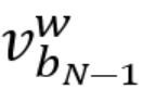
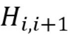
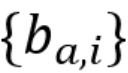
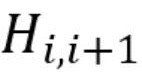





 400-4929-0909
 contact@catarc.com.cn

