Content of the invention
The invention aims to provide a vehicle pitch angle estimation method and system. The computer device and the storage medium are used for solving the problem that the estimation precision of the vehicle pitch angle estimation is not high at present according to the existing other vehicle sensor signals without increasing the hardware cost of the vehicle.
The first An embodiment of the present invention provides a vehicle pitch angle estimation method.
The current vehicle speed of the vehicle is obtained, first longitudinal acceleration is obtained according to the current vehicle speed.
The current gradient angle is acquired, and the vehicle acceleration sensor detects second longitudinal acceleration currently detected.
Based on the first longitudinal acceleration, the current gradient angle, second longitudinal acceleration, the measurement pitch angle is obtained.
The measurement pitch angle is used as an observation variable, and a pitch angle estimation value of the vehicle is obtained by performing Kalman filtering.
In an alternative, the acceleration is based on the first longitudinal acceleration. The current gradient angle and second longitudinal acceleration obtain a measured pitch angle, as shown in the following formula.
![]()
In which θ iss Measuring pitch angle, axs Longitudinal acceleration of second ax For first longitudinal acceleration, α is the slope angle, g is gravitational acceleration.
In an alternative, when the current time k is set, k time observation variable is y (k), the Kalman filtering is performed to obtain a pitch angle estimation value of the vehicle.
Performing one-step state prediction to obtain k-time-time state prediction amount ![]() Wherein.
Wherein. ![]()
![]()
![]() At k - 1, the system state quantity, u (k-1), is the value of k - type time u, F. x For the vehicle longitudinal force, h is the vehicle mass center height, m is vehicle sprung mass, M is vehicle total mass, I 'y Equivalent rotational inertia of vehicle My For vehicle pitch drag torque, T is the step size.
At k - 1, the system state quantity, u (k-1), is the value of k - type time u, F. x For the vehicle longitudinal force, h is the vehicle mass center height, m is vehicle sprung mass, M is vehicle total mass, I 'y Equivalent rotational inertia of vehicle My For vehicle pitch drag torque, T is the step size.
The process noise Q (k-1) at k - is obtained and a Q-time variance premeasure k (1, k-P) is obtained according to the process noise k (k-1), where P (k, k-1) = GP (k-1) G ''' + Q (P k k-1 1) is k -timing variance.
Observation noise k (R) at k time is acquired, and state prediction according to k time is obtained. ![]() The variance is pre-measured P (k, k-1). The observation variable y (k) and observes the noise R (k) estimates k the system state quantity at the moment of time.
The variance is pre-measured P (k, k-1). The observation variable y (k) and observes the noise R (k) estimates k the system state quantity at the moment of time. ![]() Wherein.
Wherein. ![]() C 1 0 [K], k (= P) 1 (k, k-1) C / [C··P (k, k-k) ·C C C C + R ()].
C 1 0 [K], k (= P) 1 (k, k-1) C / [C··P (k, k-k) ·C C C C + R ()].
System state quantities according to said k times ![]() A pitch angle estimate of the vehicle k is obtained.
A pitch angle estimate of the vehicle k is obtained.
In an alternative, the acquisition k instant observation noise R (k) comprises:
At k times, the observed noise first (and 1st) at k is determined by R longitudinal acceleration k longitudinal acceleration versus observed noise correlation.
Alternatively, the observed noise k (2nd) at and second time is determined based on the corresponding relationship k longitudinal acceleration R of k longitudinal acceleration and observed noise.
The second An embodiment of the present invention provides a vehicle pitch angle estimation system.
The first Signal acquisition unit for obtaining the current vehicle speed of vehicle to obtain first longitudinal acceleration according to the current vehicle speed.
The second Signal acquisition unit for obtaining current slope angle, vehicle acceleration sensor current detected second longitudinal acceleration.
The observation variable acquisition unit obtains the measurement pitch angle according to the first longitudinal acceleration, the current slope angle and second longitudinal acceleration. and
The kalman filtering unit is used for obtaining the pitch angle estimation value of the vehicle by performing Kalman filtering on the measured pitching angle as an observation variable.
In an alternative, the observation variable acquisition unit is specifically configured to obtain a measurement pitch angle according to a formula.
![]()
In which θ iss Measuring pitch angle, axs Longitudinal acceleration of second ax For first longitudinal acceleration, α is the slope angle, g is gravitational acceleration.
In an alternative, the Kalman filtering unit specifically comprises:
One-step state prediction unit for performing one-step state prediction to obtain k-time-time state prediction amount ![]() Here, k time represents the current time.
Here, k time represents the current time. ![]()
![]()
![]() At k - 1, the system state quantity, u (k-1), is the value of k - type time u, F. x For the vehicle longitudinal force, h is the vehicle mass center height, m is vehicle sprung mass, M is vehicle total mass, I 'y Equivalent rotational inertia of vehicle My For vehicle pitch drag torque, T is the step size.
At k - 1, the system state quantity, u (k-1), is the value of k - type time u, F. x For the vehicle longitudinal force, h is the vehicle mass center height, m is vehicle sprung mass, M is vehicle total mass, I 'y Equivalent rotational inertia of vehicle My For vehicle pitch drag torque, T is the step size.
A one-step variance prediction unit is used for obtaining the process noise Q (k-1) at the time of k - and obtaining Q time variance prediction k (1, k-P) according to the process noise k (k-1), wherein P (k, k-1) = GP (k-k 1 1) and k (1-P) are k .
A system state amount estimation unit for acquiring observation noise k (R) at k time and predicting an amount according to a state of k time. ![]() The variance is pre-measured P (k, k-1). The observation variable y (k) and observes the noise R (k) estimates k the system state quantity at the moment of time.
The variance is pre-measured P (k, k-1). The observation variable y (k) and observes the noise R (k) estimates k the system state quantity at the moment of time. ![]() Wherein.
Wherein. ![]() C 1 0 [K], k (= P) 1 (k, k-1) C / [C··P (k, k-k) ·C C C C + R ()]. and
C 1 0 [K], k (= P) 1 (k, k-1) C / [C··P (k, k-k) ·C C C C + R ()]. and
Pitch angle estimation unit for estimating system state quantity at k times ![]() A pitch angle estimate of the vehicle k is obtained.
A pitch angle estimate of the vehicle k is obtained.
In an alternative, the system state quantity estimation unit is further used for:
At k times, the observed noise first (and 1st) at k is determined by R longitudinal acceleration k longitudinal acceleration versus observed noise correlation.
Alternatively, the observed noise k (2nd) at and second time is determined based on the corresponding relationship k longitudinal acceleration R of k longitudinal acceleration and observed noise.
The third An embodiment of the invention provides a computer device comprising: a vehicle pitch angle estimation system according to an embodiment 2nd. Alternatively, a memory and a processor having computer readable instructions stored therein that, when executed by the processor, cause the processor to perform the steps of the vehicle pitch angle estimation method according first aspect embodiments.
The fourth An embodiment of the present invention provides a computer readable storage medium having stored thereon a computer program that, when executed by a processor, implements the steps of the vehicle pitch angle estimation method described in first aspect embodiments.
The above embodiments have at least the following beneficial effects.
When the vehicle pitch angle estimation is performed, first longitudinal acceleration obtained by the current vehicle speed derivation is fully considered. The gradient angle and of the current road detects second longitudinal acceleration currently detected by the vehicle acceleration sensor, obtains a measurement pitch angle according to the first longitudinal acceleration, the current slope angle, second longitudinal acceleration, and carries out Kalman filtering to obtain the pitch angle estimation value of the vehicle. , Under the condition that the hardware cost of the vehicle is not increased, the problem of low estimation accuracy existing in the vehicle pitch angle estimation according to the existing other vehicle sensor signals is solved.
Features and advantages of the invention will be set forth in the description which follows and, in part, will be obvious from the description, or may be embodied by practice of the invention. The objectives and other advantages of the invention may be realized and attained by the structure particularly pointed out in the written description and claims and.
Mode of execution
Various exemplary embodiments, features, and aspects of the present disclosure will be described in detail below with reference to the accompanying drawings. Like reference numerals in the drawings denote identical or similar elements. While various aspects of the embodiments are shown in the drawings, the drawings are not necessarily drawn to scale unless specifically noted.
In addition, in order to better illustrate the present invention, numerous specific details are set forth in the detailed description that follows. It should be understood by those skilled in the art that the present invention may be practiced without some specific details. In some instances, well-known means to those skilled in the art are not described in detail in order to highlight the subject matter of the present invention.
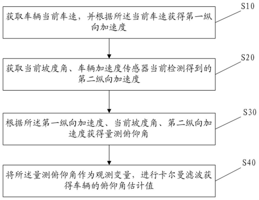
As shown 1, an embodiment of the present invention provides a method for estimating a pitch angle of a vehicle, which comprises the following steps S10 - S40:
Step S10: obtaining a current vehicle speed of the vehicle and obtaining first longitudinal acceleration according to the current vehicle speed.
, In step S10, a longitudinal component of the current vehicle speed is obtained first longitudinal acceleration, and the current vehicle speed of the vehicle can be acquired through CAN bus acquisition.
In step S20, the current gradient angle is acquired, and the vehicle acceleration sensor detects second longitudinal acceleration currently detected.
, The current gradient angle may be acquired from the map by GPS navigation information, the map data including the gradient angle information of each road, and thus the gradient angle of the road where the corresponding vehicle is located may be obtained according to the vehicle position information. Of course, other methods for estimating the gradient angle may be used for real-time estimation, and the method of acquiring the gradient angle in the present embodiment is not specifically limited, and is all within the protection scope of the present invention.
In general, the vehicle is equipped with a vehicle acceleration sensor (e.g. an inertial sensor in ESP) for detecting vehicle longitudinal acceleration, and the longitudinal acceleration detected by the vehicle acceleration sensor in the present embodiment is defined as second longitudinal acceleration.
Step S30. Based on the first longitudinal acceleration, the current gradient angle, second longitudinal acceleration, the measurement pitch angle is obtained.
, The vehicle pitch angle variation mainly causes the suspension deformation to be changed due to the change in the load of the front and rear shafts, thereby causing the vehicle to lean forward or tilt. , The vehicle pitch can be estimated by estimating the front-rear axle load and combining the suspension characteristics. Because the vertical rigidity of the tire is obviously higher than the vertical rigidity of the suspension frame, the attitude of the lower mass of the vehicle spring during driving is assumed to be constant, and the vehicle pitching one-dimensional kinetic equation is as shown in Equation (1).
![]()
Here, θ is a pitch angle. ![]() -pitch angular F accelerationx The longitudinal force, h is the mass center height, m is the sprung mass, M is the total mass of vehicle, I '. y M For equivalent rotational inertiay A pitch drag torque.
-pitch angular F accelerationx The longitudinal force, h is the mass center height, m is the sprung mass, M is the total mass of vehicle, I '. y M For equivalent rotational inertiay A pitch drag torque.
I 'y = Iy + Mmh2 (2)
In-flight Iy The rotational inertia of the vehicle around y axis can be obtained by measuring in advance.
Fx = m·ax (3)
In-flight ax For vehicle longitudinal acceleration, it is possible to derive by longitudinal vehicle speed.
![]()
In-flight l1 Distance between front axle and centroid in X direction, l2 Distance of rear axle and centroid in X direction, K1 , K2 Spring rigidity and R for suspension of front axle and rear axle respectively1 , R2 Shock and back damper characteristics, respectively.
, The center of gravity height and the center of mass X in the vehicle design state can be acquired through Y bench tests around KC-axis rotational inertia. The vehicle pitch angle can be estimated by combining the suspension characteristics, the vehicle longitudinal acceleration, and the vehicle longitudinal acceleration when the vehicle is half-loaded. However, since the actual load of the vehicle is frequently changed, the position of the center of gravity also changes correspondingly, the formula (1) has certain uncertainty, and therefore, the pitching angle is estimated by the longitudinal acceleration measured by the longitudinal sensor and the deviation of the actual longitudinal acceleration of the vehicle.
The inertial sensor ESP installed in the vehicle X coincides with the vehicle X axis, and the variation in the pitch angle of the vehicle causes first longitudinal acceleration a. x Longitudinal acceleration second with axs Deviation, ax AND axs The relationship is as follows.
![]()
In-flight lc The sensor is transversely offset from the center of rotation during cornering. ![]() For yaw angular acceleration, r is the yaw rate, V. y To Y speed, g is gravitational acceleration, α is the slope angle. If the influence of the transverse pendulum motion is ignored, there are:
For yaw angular acceleration, r is the yaw rate, V. y To Y speed, g is gravitational acceleration, α is the slope angle. If the influence of the transverse pendulum motion is ignored, there are:
axs = ax Cos θ θ θ θ + g sin (α + θ) (6)
From Equation (6), according to the first longitudinal acceleration, the current slope angle, second longitudinal acceleration, a measured pitch angle can be obtained.
Step S40: A pitch angle estimated value of the vehicle is obtained by performing Kalman filtering on the measured pitch angle as an observation variable.
Based on first longitudinal acceleration, current gradient angle, and longitudinal acceleration, and second longitudinal acceleration obtained from the current vehicle speed, the measured pitch angle is obtained as an observation variable, and the pitch angle estimation value of the vehicle is obtained by Kalman filtering first 2nd. , Under the condition that the hardware cost of the vehicle is not increased, the problem of low estimation accuracy existing in the vehicle pitch angle estimation according to the existing other vehicle sensor signals is solved.
In a preferred embodiment, the measured pitch angle is obtained from the first longitudinal acceleration, the current slope angle, second longitudinal acceleration, as shown in the following formula.
![]()
In which θ iss Measuring pitch angle, axs Longitudinal acceleration of second ax For first longitudinal acceleration, α is the slope angle, g is gravitational acceleration.
, Based on Equation (6), the pitch angle of the most operating vehicle is considered to be below 3°, cos θ ≈ 1, and thus the pitching angle observed by the sensor is as shown in Equation (7).
In a preferred embodiment, vehicle pitch angle estimation is carried out by Kalman filtering, system equation modeling is performed based on formula (1), and system state vectors are made. ![]()
![]() The observation variable y is a pitch angle θ. s The system state space equation is: the system state space equation.
The observation variable y is a pitch angle θ. s The system state space equation is: the system state space equation.
![]()
Wherein. ![]() C 1 0
C 1 0
In matrix A. ![]()
The formula (8) is discretized and obtained.
![]()
Wherein. ![]() T Is a step size, that is, the time interval between the current cycle estimated for the pitch angle and the last cycle, which is a preset parameter value.
T Is a step size, that is, the time interval between the current cycle estimated for the pitch angle and the last cycle, which is a preset parameter value.
Based on the Kalman filtering model considering the vehicle model above, the current time k time is set, k time observation variable is y (k), and the step S40 specifically includes the following steps.
Step S401, performing one-step state prediction to obtain k-time-time state prediction amount ![]() Wherein.
Wherein. ![]()
![]() For k - a system state quantity, u (k-1) is the value of k -timing u.
For k - a system state quantity, u (k-1) is the value of k -timing u.
Step S402: The process noise Q (k-1) at k - is acquired, and a Q-time variance prediction k (1, k-P) is obtained according to the process noise k (k-1), where P (k, k-1) = GP (k-1) G ''' + Q P (k k 1-1) is k -timing variance.
Step S403. Observation noise k (R) at k time is acquired, and state prediction according to k time is obtained. ![]() The variance prediction P (k, k-1), the observed variable y (k) and, and the observed noise R (k) estimate k time system state quantities.
The variance prediction P (k, k-1), the observed variable y (k) and, and the observed noise R (k) estimate k time system state quantities. ![]() Wherein.
Wherein.
![]() K (k) Is a filter gain matrix, K (k) = P (k, k-1) C / [C··P (k, k-1) ·C C C C + R (k)].
K (k) Is a filter gain matrix, K (k) = P (k, k-1) C / [C··P (k, k-1) ·C C C C + R (k)].
Step S404: The variance update at k times P (k, k-1) performs variance update to obtain k time variance P (k) and holds, P (k) = [I-K(k) ·C] ·P (k, k-1), I. Wherein, k time variance P (k) is used for follow-up k + 1 timing depression angle estimation.
Step S405. System state quantities according to said k times ![]() A pitch angle estimate of the vehicle k is obtained.
A pitch angle estimate of the vehicle k is obtained.
, In step S405, system state quantities at times of CX and k are determined according to observation matrix y ![]() In other words, k times the pitch angle estimated value of the vehicle is obtained.
In other words, k times the pitch angle estimated value of the vehicle is obtained.
In particular, with respect to a Kalman filter model of the existing pitch angle, the Kalman filtering model in this embodiment takes into account the dynamics factors of the pitch angle variation, combines the measured pitch angle of the sensor measurement data estimation with the one-dimensional kinetic model estimation pitch angle, and further improves the accuracy of the pitch angle estimation value.
In a preferred embodiment, the acquisition k instant observation noise R (k) comprises:
At k times, the observed noise first (and 1st) at k is determined by R longitudinal acceleration k longitudinal acceleration versus observed noise correlation.
Alternatively, the observed noise k (2nd) at and second time is determined based on the corresponding relationship k longitudinal acceleration R of k longitudinal acceleration and observed noise.
, The longitudinal acceleration of the vehicle and the observed noise have a certain relationship, and the corresponding relationship may be generally described as: when the longitudinal acceleration of the vehicle is not large in the linear motion, a smaller value is given to the measured noise variance. When the vehicle lateral acceleration is large and the longitudinal acceleration changes violently, a larger value is given to the measured noise variance.
It needs to be noted that the correspondence relationship is preliminarily calibrated according to the real vehicle measurement data, and the corresponding relation of different vehicle types is different. Since first longitudinal acceleration and second longitudinal acceleration are taken into account in the present embodiment, the observation noise first (2nd) at k time may be determined individually in consideration R longitudinal acceleration and the corresponding relationship of k longitudinal acceleration and observed noise, and first longitudinal acceleration may be comprehensively considered. The second Longitudinal acceleration and observation noise's corresponding relation, the factor that specifically considered carries out real vehicle measurement data calibration and obtains corresponding relation to be used for observation noise R (k)'s acquisition.
As shown 2, an embodiment of the present invention provides a vehicle pitch angle estimation system.
The first Signal acquisition unit 1 is used for acquiring the current vehicle speed of the vehicle and obtaining first longitudinal acceleration according to the current vehicle speed.
The second Signal acquisition unit 2 is used for obtaining current slope angle, and the current detected second longitudinal acceleration of vehicle acceleration sensor.
The observation variable acquisition unit 3 obtains a measurement pitch angle according to the first longitudinal acceleration, the current slope angle, second longitudinal acceleration. and
The Kalman filtering unit 4 is configured to obtain a pitch angle estimated value of the vehicle by performing Kalman filtering on the measured pitch angle as an observation variable.
In a preferred embodiment, the observation variable acquisition unit 3 is specifically configured to obtain a measurement pitch angle according to a formula.
![]()
In which θ iss Measuring pitch angle, axs Longitudinal acceleration of second ax For first longitudinal acceleration, α is the slope angle, g is gravitational acceleration.
In a preferred embodiment, the Kalman filtering unit 4 specifically comprises:
One-step state prediction unit 41 for performing one-step state prediction to obtain k-time-time state prediction amount ![]() Here, k time represents the current time.
Here, k time represents the current time. ![]()
![]()
![]() At k - 1, the system state quantity, u (k-1), is the value of k - type time u, F. x For the vehicle longitudinal force, h is the vehicle mass center height, m is vehicle sprung mass, M is vehicle total mass, I 'y Equivalent rotational inertia of vehicle My For the pitch drag torque of the vehicle, T is the step size, that is, the time interval between the current cycle of the program and the previous cycle.
At k - 1, the system state quantity, u (k-1), is the value of k - type time u, F. x For the vehicle longitudinal force, h is the vehicle mass center height, m is vehicle sprung mass, M is vehicle total mass, I 'y Equivalent rotational inertia of vehicle My For the pitch drag torque of the vehicle, T is the step size, that is, the time interval between the current cycle of the program and the previous cycle.
One-step variance prediction unit 42 is used to acquire the process noise Q (k-1) at the time of k - 1 and obtain Q-time variance prediction k (1, k-P) at the time of one-step prediction on the process noise k (k-1), where P (1 k, k k k 1-1) G P '1' ' + Q (= GP-k) is k .
A system state amount estimation unit 43 acquires observation noise k (R) at k time, and estimates the state prediction according to k times. ![]() The variance is pre-measured P (k, k-1). The observation variable y (k) and observes the noise R (k) estimates k the system state quantity at the moment of time.
The variance is pre-measured P (k, k-1). The observation variable y (k) and observes the noise R (k) estimates k the system state quantity at the moment of time. ![]() Wherein.
Wherein. ![]() C 1 0 [K], k (= P) 1 (k, k-1) C / [C··P (k, k-k) ·C C C C + R ()].
C 1 0 [K], k (= P) 1 (k, k-1) C / [C··P (k, k-k) ·C C C C + R ()].
The variance estimation unit 44 estimates k (P, k-k) variance updates at 1 times to obtain k time variance P (k), P (k) = [I-K(k) ·C] ·P (k, k-1), I. and
Pitch angle estimation unit 45 for estimating system state quantities based on said k times ![]() And Variance P (k) At k times the pitch angle estimate of the vehicle is obtained.
And Variance P (k) At k times the pitch angle estimate of the vehicle is obtained.
In a preferred embodiment, the system state quantity estimation unit 43 is specifically also used for:
At k times, the observed noise first (and 1st) at k is determined by R longitudinal acceleration k longitudinal acceleration versus observed noise correlation.
Alternatively, the observed noise k (2nd) at and second time is determined based on the corresponding relationship k longitudinal acceleration R of k longitudinal acceleration and observed noise.
Alternatively, k longitudinal acceleration according to first times. The second Longitudinal acceleration and first longitudinal acceleration, second longitudinal acceleration and observed noise correlation determine k-time observation noise R (k).
The system embodiments described above are illustrative only, wherein the elements illustrated as separate components may or may not physically separate, may or may not be physical units, i.e. may be located in one place, or may also be distributed over multiple network elements. Part or all of the modules can be selected according to actual needs to achieve the object of the embodiment of the present embodiment.
It should be noted that the system according to the above-mentioned embodiment corresponds to the method described in the above-mentioned embodiment, and therefore, the system not described in detail in the above-mentioned embodiments can be obtained by reference to the contents of the method described above.
Also, the vehicle pitch angle estimation system described in the above embodiment may be stored in a computer-readable storage medium if implemented in the form of a software functional unit and sold or used as a separate product.
Another embodiment of the present invention further provides a computer device, comprising: the vehicle pitch angle estimation system according to the above embodiment. Alternatively, the memory and the processor, the memory stores therein computer readable instructions which, when executed by the processor, cause the processor to perform the steps of the vehicle pitch angle estimating method according to the embodiments described above.
Of course, the computer device may also have a wired or wireless network interface. The keyboard and is input to an output interface or the like so as to perform an input/output, and the computer device may further include other components for implementing the functions of the device, which will not be described in detail herein.
, The computer program may be divided into one or more units that are stored in the memory and executed by the processor to complete the present invention. The one or more units may be a series of computer program instruction segments capable of performing a particular function for describing an execution process of the computer program in the computer device.
The processor may be a central processing unit (Central Processing Unit, CPU), other general purpose processors, digital signal processors (Digital Signal Processor, DSP), specific integrated circuits (Application Specific Integrated Circuit, ASIC), existing programmable gate arrays (Field-Programmable Gate Array, FPGA), or other programmable logic devices, discrete gates or transistor logic devices, discrete hardware components, and the like. A general purpose processor may be a microprocessor or the processor may be any conventional processor or the like, the processor being a control center of the computer device, connecting the entire computer device with various interfaces and lines.
The memory may be used to store the computer program and/or unit that, by running or executing a computer program and/or a unit stored in the memory, and invokes data stored in a memory to implement various functions of the computer device. In addition, the memory may include a high speed random access memory, and may also include non-volatile memory such as hard disk, memory, plug-in hard disk, smart memory card (Smart Media Card, SMC), secure digital (Secure Digital, SD) card, flash memory card (Flash Card), at least one disk storage device, flash memory device, or other volatile solid state storage device.
Another embodiment of the present invention further provides a computer-readable storage medium having stored thereon a computer program which, when executed by a processor, implements the steps of the method for estimating the pitch angle of the vehicle according to the embodiment described above.
, The computer readable storage medium may include any entity or device, recording medium, U disk, mobile hard disk, magnetic disk, optical disk, computer memory, read only memory (ROM, Read-Only Memory), random access memory (RAM, Random Access Memory), a carrier signal, a telecommunication signal and software distribution medium, and the like that can carry the computer program code.
While various embodiments of the present invention have been described above, the foregoing description is exemplary and is not intended to be exhaustive or limited to the disclosed embodiments. Many modifications and variations will be apparent to those of ordinary skill in the art without departing from the scope and spirit of the described embodiments. The terminology used herein is for the purpose of best explaining the principles of the embodiments, the actual application, or technical improvements in the market, or to enable others of ordinary skill in the art to understand the embodiments disclosed herein.


 400-4929-0909
 contact@catarc.com.cn

