当前位置: 首页> 专利交易> 详情页
    待售中

    一种点云数据的可视化处理方法和装置[ZH]

    专利编号: ZL202609180122

    收藏

    拟转化方式: 转让;普通许可;独占许可;排他许可;开放许可

    交易价格:面议

    专利类型:发明专利

    法律状态:授权

    技术领域:智能网联汽车

    发布日期:2026-09-18

    发布有效期: 2026-09-18 至 2042-09-16

    专利顾问 — 王老师

    电话咨询

    咨询电话

    13760886304

    专利基本信息
    >
    申请号 CN202211125223.1 公开号 CN115205434A
    申请日 2022-09-16 公开日 2022-10-18
    申请人 中汽创智科技有限公司 专利授权日期 2022-12-16
    发明人 蔡香玉;李建昆;周勋;胡帅朋;龚小鹏;张灿;胡伟 专利权期限届满日 2042-09-16
    申请人地址 211100 江苏省南京市江宁区秣陵街道胜利路88号 最新法律状态 授权
    技术领域 智能网联汽车 分类号 G06T15/00
    技术效果 安全性 有效性 有效(授权、部分无效)
    专利代理机构 广州三环专利商标代理有限公司 44202 代理人 郑华洁
    专利技术详情
    >
    01

    专利摘要

    本发明涉及了一种点云数据的可视化处理方法和装置,该方法包括:根据待处理的点云数据的属性信息确定点云数据对应的视景体,得到点云数据对应的视界;获取视界覆盖范围内的点云网格,得到第一点云网格集合;将视界包含的区域划分为第一数量层同心圆环;基于计算机实时的帧率,确定各个第一点云网格当前能够加载的实际点云数量,并将实际点云数量的点云数据,按照同心圆环分层次依次加载到计算机的内存中;对已加载的点云数据逐个进行渲染处理,得到待处理的点云数据的可视化展示结果。上述方案可以保证在不超出计算机当前处理能力的情况下,安全的加载和渲染点云数据,不会出现延时、卡顿和运行崩溃现象,提高了点云数据的处理能力。
    展开 >
    02

    专利详情

    技术领域

    本发明涉及点云数据处理技术领域,尤其涉及一种点云数据的可视化处理方法和装置。

    背景技术

    近年来,随着激光雷达技术的快速发展和日益广泛的应用,极大地增强了人们获取真实世界三维数据的能力,通过激光雷达可以获取丰富的反映真实世界的点云数据,推动了三维重建、虚拟现实等技术迅速发展。

    三维点云数据是用三维坐标数据表征的许多点的集合。激光雷达获取三维点云数据后,设计算法用计算机对点云数据进行处理,便可以得到所需要的数字产品。高效地组织和管理点云数据是高效地处理和应用点云数据的基础,不同的处理和应用要求,会采用不同的点云数据组织方法,通常有网格化、四叉树、八叉树数据组织形式。

    然而,通过三维激光雷达获取大面积的地形地物数据时,往往会得到海量的激光点云数据。当计算机采用上述传统方法加载和渲染这些点云数据时,内存开销会很大,并且会存在延时和卡顿现象。尤其当点云数据的大小超过了计算机内存时,会出现计算机无法加载和可视化点云数据、程序崩溃的现象。

    由此可见,现有技术还不能对海量的点云数据进行安全的可视化处理,对于点云数据的处理效率不高。

    发明内容

    本发明旨在至少解决现有技术中存在的技术问题之一。为此,本发明第一方面提出一种点云数据的可视化处理方法,所述方法包括:

    根据待处理的点云数据的属性信息确定所述点云数据对应的视景体,并确定所述视景体在所述点云数据对应的平面点云网格上的投影,得到所述点云数据对应的视界;

    获取所述视界覆盖范围内的点云网格,得到第一点云网格集合;

    将所述视界包含的区域划分为第一数量层同心圆环,所述同心圆环以所述视界的中心为圆心;

    基于计算机实时的帧率,确定各个所述第一点云网格当前能够加载的实际点云数量,并将所述实际点云数量的点云数据,按照所述同心圆环分层次依次加载到计算机的内存中;

    对已加载的所述点云数据逐个进行渲染处理,得到所述待处理的点云数据的可视化展示结果。

    可选的,所述确定各个所述第一点云网格当前能够加载的实际点云数量,包括:

    确定当前待加载的目标同心圆环所在层对应的期望加载权重和与所述期望加载权重对应的多个候选加载权重;

    分别获取所述目标同心圆环中包括的各个第二点云网格与所述视点之间的距离,得到目标距离;

    获取各个所述第二点云网格中包括的点云数量,得到第二数量;

    基于所述期望加载权重、所述候选加载权重、所述目标距离、所述第二数量以及所述计算机实时的帧率,确定所述计算机能够加载的所述第二点云网格中的实际点云数量。

    可选的,所述基于所述期望加载权重、所述候选加载权重、所述目标距离、所述第二数量以及计算机实时的帧率,确定所述计算机能够加载的所述第二点云网格中的实际点云数量,包括:

    根据当前层的点云的总数量和所述候选加载权重,确定每个所述候选加载权重对应的点云的显示数量,得到多个候选加载数量;

    根据所述计算机实时的加载速度确定加载所述候选加载数量个点云数据对应的候选耗时,得到多个候选耗时;

    从所述多个候选耗时中选取小于所述计算机的刷新耗时的至少一个目标候选耗时;所述刷新耗时根据所述实时的帧率确定;

    从所述至少一个目标候选耗时对应的目标候选加载权重中,插值得到当前的实际加载权重;

    根据所述实际加载权重、所述目标距离和所述第二数量,确定所述计算机能够加载的所述第二点云网格中的实际点云数量。

    可选的,所述根据所述实际加载权重、所述目标距离和所述第二数量,确定所述计算机能够加载的所述第二点云网格中的实际点云数量,包括:

    根据所述目标距离和距离系数,得到目标关系距离;

    根据所述目标关系距离和所述实际加载权重的乘积,得到消耗系数;

    取所述消耗系数和1两者中的较小值,得到增量期望;

    根据所述第二数量和所述增量期望的乘积,得到所述计算机能够加载的所述第二点云网格中的实际点云数量。

    可选的,所述将所述实际点云数量的点云数据,按照所述同心圆环分层次依次加载到计算机的内存中,包括:

    确定所述目标同心圆环中包括的各个第二点云网格的第二网格编号;

    确定所述第二网格编号对应的目标索引信息,并按照所述目标索引信息从点云存储文件中获取所述实际点云数量的点云数据在所述点云存储文件中的目标位置;

    将所述目标位置的点云数据加载到所述计算机的内存中。

    可选的,所述根据待处理的点云数据的属性信息确定所述点云数据对应的视景体,包括:

    从点云索引文件中获取待处理的点云数据的属性信息,所述属性信息包括所述点云数据对应的网格坐标系的原点坐标、点云网格边长、平面点云网格的最大编号、所述点云数据的最大Z轴坐标;

    根据所述网格坐标系的原点坐标、所述点云网格边长、所述平面点云网格的最大编号、所述最大Z轴坐标和预设的视点的Z坐标的相对高度,确定所述点云数据的视点的初始坐标;

    以所述视点的初始坐标作为坐标系原点,构建视点坐标系;

    将所述视点坐标系下的X轴和Y轴方向的张角形成的视野窗口确定为视口;

    将所述视点到所述视口的中心的连线向量的方向确定为视向;

    将所述视点与所述视口在所述视向方向上构成的立体图形,确定为所述点云数据对应的视景体。

    可选的,在对已加载的所述点云数据逐个进行渲染处理之前,还包括:

    对当前视图下可视区域以外的点云数据进行剔除。

    可选的,若所述当前视图为正交视图,则所述当前视图下可视区域以外的点云数据至少包括:

    所述视景体的奥卡托投影区域外的点云网格包括的点云数据、所述视景体与窗口视图比例大于第一预设比例且视角中心至所述点云网格的中心的距离大于第一预设距离的点云数据、所述视景体与窗口视图比例大于第二预设比例的点云网格包括的点云数据。

    可选的,若所述当前视图为自由视图,则所述当前视图下可视区域以外的点云数据至少包括:

    所述视景体以外区域的点云网格包括的点云数据、所述点云网格的中心到所述视点的距离大于第三距离的点云网格包括的点云数据、所述视点至所述视景体的中心的距离大于第二预设距离时全部的点云数据;所述第三距离为所述视景体的中心到所述视点的距离与预设参考距离的和。

    可选的,所述对已加载的所述点云数据逐个进行渲染处理,包括:

    利用顶点着色器和片段着色器对所述点云数据逐个进行渲染处理。

    可选的,在得到所述待处理的点云数据的可视化展示结果之后,还包括:

    当检测到所述视口的朝向和所述视点到所述视景体中的点云的距离发生变化时,重新获取所述点云数据的属性信息,得到新属性信息;

    根据所述新属性信息确定所述点云数据对应的新视景体,并确定所述新视景体在所述点云数据对应的平面点云网格上的投影,得到所述点云数据对应的新视界;

    获取所述新视界覆盖范围内的点云网格,得到第三点云网格集合;

    将所述第三点云网格集合中新增的点云数据加载到所述内存中。

    可选的,所述将所述第三点云网格集合中新增的点云数据加载到所述内存中,包括:

    获取所述第一点云网格集合中的点云网格的第一网格编号,和所述第三点云网格集合中的点云网格的第三网格编号;

    获取在所述第一网格编号中存在、而在所述第三网格编号中不存在的差异网格编号,获取在所述第一网格编号中不存在,而在所述第三网格编号中存在的新增网格编号,并获取在所述第一网格编号和所述第三网格编号中均存在的相同网格编号;

    从已加载到所述内存中的点云数据中,删除所述差异网格编号对应的点云数据,保留所述相同网格编号对应的点云数据,并加载所述新增点云数据。

    本发明第二方面提出一种点云数据的可视化处理装置,所述装置包括:

    视界确定模块,用于根据待处理的点云数据的属性信息确定所述点云数据对应的视景体,并确定所述视景体在所述点云数据对应的平面点云网格上的投影,得到所述点云数据对应的视界;

    第一点云网格集合获取模块,用于获取所述视界覆盖范围内的点云网格,得到第一点云网格集合;

    同心圆环划分模块,用于将所述视界包含的区域划分为第一数量层同心圆环,所述同心圆环以所述视界的中心为圆心;

    分层加载模块,用于基于计算机实时的帧率,确定各个所述第一点云网格当前能够加载的实际点云数量,并将所述实际点云数量的点云数据,按照所述同心圆环分层次依次加载到计算机的内存中;

    渲染处理模块,用于对已加载的所述点云数据逐个进行渲染处理,得到所述待处理的点云数据的可视化展示结果。

    可选的,所述分层加载模块具体用于:

    确定当前待加载的目标同心圆环所在层对应的期望加载权重和与所述期望加载权重对应的多个候选加载权重;

    分别获取所述目标同心圆环中包括的各个第二点云网格与所述视点之间的距离,得到目标距离;

    获取各个所述第二点云网格中包括的点云数量,得到第二数量;

    基于所述期望加载权重、所述候选加载权重、所述目标距离、所述第二数量以及所述计算机实时的帧率,确定所述计算机能够加载的所述第二点云网格中的实际点云数量。

    可选的,所述分层加载模块进一步用于:

    根据当前层的点云的总数量和所述候选加载权重,确定每个所述候选加载权重对应的点云的显示数量,得到多个候选加载数量;

    根据所述计算机实时的加载速度确定加载所述候选加载数量个点云数据对应的候选耗时,得到多个候选耗时;

    从所述多个候选耗时中选取小于所述计算机的刷新耗时的至少一个目标候选耗时;所述刷新耗时根据所述实时的帧率确定;

    从所述至少一个目标候选耗时对应的目标候选加载权重中,插值得到当前的实际加载权重;

    根据所述实际加载权重、所述目标距离和所述第二数量,确定所述计算机能够加载的所述第二点云网格中的实际点云数量。

    可选的,所述分层加载模块进一步用于:

    根据所述目标距离和距离系数,得到目标关系距离;

    根据所述目标关系距离和所述实际加载权重的乘积,得到消耗系数;

    取所述消耗系数和1两者中的较小值,得到增量期望;

    根据所述第二数量和所述增量期望的乘积,得到所述计算机能够加载的所述第二点云网格中的实际点云数量。

    可选的,所述分层加载模块进一步用于:

    确定所述目标同心圆环中包括的各个第二点云网格的第二网格编号;

    确定所述第二网格编号对应的目标索引信息,并按照所述目标索引信息从点云存储文件中获取所述实际点云数量的点云数据在所述点云存储文件中的目标位置;

    将所述目标位置的点云数据加载到所述计算机的内存中。

    可选的,所述视界确定模块具体用于:

    从点云索引文件中获取待处理的点云数据的属性信息,所述属性信息包括所述点云数据对应的网格坐标系的原点坐标、点云网格边长、平面点云网格的最大编号、所述点云数据的最大Z轴坐标;

    根据所述网格坐标系的原点坐标、所述点云网格边长、所述平面点云网格的最大编号、所述最大Z轴坐标和预设的视点的Z坐标的相对高度,确定所述点云数据的视点的初始坐标;

    以所述视点的初始坐标作为坐标系原点,构建视点坐标系;

    将所述视点坐标系下的X轴和Y轴方向的张角形成的视野窗口确定为视口;

    将所述视点到所述视口的中心的连线向量的方向确定为视向;

    将所述视点与所述视口在所述视向方向上构成的立体图形,确定为所述点云数据对应的视景体。

    可选的,所述装置还包括:

    剔除模块,用于对当前视图下可视区域以外的点云数据进行剔除。

    可选的,若所述当前视图为正交视图,则所述当前视图下可视区域以外的点云数据至少包括:

    所述视景体的奥卡托投影区域外的点云网格包括的点云数据、所述视景体与窗口视图比例大于第一预设比例且视角中心至所述点云网格的中心的距离大于第一预设距离的点云数据、所述视景体与窗口视图比例大于第二预设比例的点云网格包括的点云数据。

    可选的,若所述当前视图为自由视图,则所述当前视图下可视区域以外的点云数据至少包括:

    所述视景体以外区域的点云网格包括的点云数据、所述点云网格的中心到所述视点的距离大于第三距离的点云网格包括的点云数据、所述视点至所述视景体的中心的距离大于第二预设距离时全部的点云数据;所述第三距离为所述视景体的中心到所述视点的距离与预设参考距离的和。

    可选的,所述渲染处理模块具体用于:

    利用顶点着色器和片段着色器对所述点云数据逐个进行渲染处理。

    可选的,所述装置还包括:

    新属性信息获取模块,用于当检测到所述视口的朝向和所述视点到所述视景体中的点云的距离发生变化时,重新获取所述点云数据的属性信息,得到新属性信息;

    新视界确定模块,用于根据所述新属性信息确定所述点云数据对应的新视景体,并确定所述新视景体在所述点云数据对应的平面点云网格上的投影,得到所述点云数据对应的新视界;

    第三点云网格集合获取模块,用于获取所述新视界覆盖范围内的点云网格,得到第三点云网格集合;

    新点云数据加载模块,用于将所述第三点云网格集合中新增的点云数据加载到所述内存中。

    可选的,所述新点云数据加载模块具体用于:

    获取所述第一点云网格集合中的点云网格的第一网格编号,和所述第三点云网格集合中的点云网格的第三网格编号;

    获取在所述第一网格编号中存在、而在所述第三网格编号中不存在的差异网格编号,获取在所述第一网格编号中不存在,而在所述第三网格编号中存在的新增网格编号,并获取在所述第一网格编号和所述第三网格编号中均存在的相同网格编号;

    从已加载到所述内存中的点云数据中,删除所述差异网格编号对应的点云数据,保留所述相同网格编号对应的点云数据,并加载所述新增点云数据。

    本发明第三方面提出一种电子设备,所述电子设备包括处理器和存储器,所述存储器种存储有至少一条指令、至少一段程序、代码集或指令集,所述至少一条指令、所述至少一段程序、所述代码集或指令集由所述处理器加载并执行以实现如第一方面所述的点云数据的可视化处理方法。

    本发明第四方面提出一种计算机可读存储介质,所述存储介质中存储有至少一条指令、至少一段程序、代码集或指令集,所述至少一条指令、所述至少一段程序、所述代码集或指令集由处理器加载并执行以实现如第一方面所述的点云数据的可视化处理方法。

    本发明实施例具有以下有益效果:

    在本发明实施例中,根据待处理的点云数据的属性信息确定所述点云数据对应的视景体,并确定所述视景体在所述点云数据对应的平面点云网格上的投影,得到所述点云数据对应的视界;获取所述视界覆盖范围内的点云网格,得到第一点云网格集合;将所述视界包含的区域划分为第一数量层同心圆环,所述同心圆环以所述视界的中心为圆心;基于计算机实时的帧率,确定各个所述第一点云网格当前能够加载的实际点云数量,并将所述实际点云数量的点云数据,按照所述同心圆环分层次依次加载到计算机的内存中;对已加载的所述点云数据逐个进行渲染处理,得到所述待处理的点云数据的可视化展示结果。上述方案基于计算机实时的帧率,确定第一点云网格能够加载的实际点云数量,并且按照同心圆环分层次进行加载和渲染,可以保证在不超出计算机当前处理能力的情况下,安全的加载和渲染点云数据,不会出现延时、卡顿和运行崩溃现象,提高了点云数据的处理能力。

    本发明的附加方面和优点将在下面的描述中部分给出,部分将从下面的描述中变得明显,或通过本发明的实践了解到。

    附图说明

    为了更清楚地说明本发明的技术方案,下面将对实施例或现有技术描述中所需要使用的附图作简单的介绍。显而易见地,下面描述中的附图仅仅是本发明的一些实施例,对于本领域普通技术人员来讲,在不付出创造性劳动的前提下,还能够根据这些附图获得其它附图。

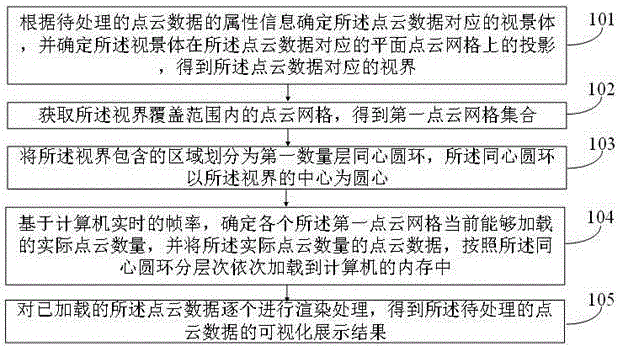
    图1为本发明实施例提供的第一种点云数据的可视化处理方法的步骤流程图;

    图2为本发明实施例提供的点云网格的示意图;

    图3为本发明实施例提供的视点坐标系下的视景体示意图;

    图4为本发明实施例提供的P0坐标系下的点云网格、视景体和视界的示意图;

    图5为本发明实施例提供的同心圆环的示意图;

    图6为本发明实施例提供的确定视景体的方法的步骤流程图;

    图7为本发明实施例提供的确定当前能够加载的实际点云数量的方法的步骤流程图;

    图8为本发明实施例提供的目标距离的示意图;

    图9为本发明实施例提供的第二种点云数据的可视化处理方法的步骤流程图;

    图10为本发明实施例提供的一种点云数据的可视化处理装置的结构框图。

    具体实施方式

    下面将结合本发明实施例中的附图,对本发明实施例中的技术方案进行清楚、完整地描述,显然,所描述的实施例仅仅是本发明一部分实施例,而不是全部的实施例。基于本发明中的实施例,本领域普通技术人员在没有做出创造性劳动的前提下所获得的所有其他实施例,都属于本发明保护的范围。

    本说明书提供了如实施例或流程图所述的方法操作步骤,但基于常规或无创造性的劳动可以包括更多或者更少的操作步骤。在实际中的系统或服务器产品执行时,可以按照实施例或者附图所示的方法顺序执行或者并行执行(例如并行处理器或者多线程处理的环境)。

    图1为本发明实施例提供的第一种点云数据的可视化处理方法的步骤流程图。该方法可以包括如下步骤:

    步骤101、根据待处理的点云数据的属性信息确定所述点云数据对应的视景体,并确定所述视景体在所述点云数据对应的平面点云网格上的投影,得到所述点云数据对应的视界。

    待处理的点云数据是指存储在点云存储文件中、待进行可视化处理的点云数据。点云存储文件对应有点云索引文件,点云索引文件用于指示点云存储文件中各个点云数据的存储位置,以及标示点云数据的各种属性信息。

    点云数据以点云网格的形式存储,点云网格的划分方法可以为:首先确定点云数据的几何边界,根据几何边界得到覆盖点云数据的外包框,然后选取合适的第一边长,将第一边长作为正方形网格的边长,将外包框划分为多个点云网格,从而得到点云数据对应的多个点云网格,各个点云网格中存储有大量的点云数据。

    从点云索引文件中获取点云数据的属性信息,通过属性信息可以确定相机所在的视点坐标,通过视点坐标得到视点坐标系,进而得到视点坐标系下X轴和Y轴坐标轴方向的张角形成的视野窗口,即视口,由视口进一步得到视向,进一步将由视点与视口在视向方向上构成的立体图形,确定为视景体。而视景体在平面点云网格上的投影为点云数据对应的视界。

    图2为本发明实施例提供的点云网格的示意图。

    参照图2,P0为边界基准点,由坐标系的X轴和Y轴围成覆盖所有点云数据的边界框。将边界框包含的区域按照第一边长划分为多个正方形网格,即得到图2中的多个点云网格。

    图3为本发明实施例提供的视点坐标系下的视景体示意图。

    参照图3,V为视点,在视点坐标系下X轴和Y轴坐标轴方向的张角和V的连线构成视野窗口ABCD,即视口。ABCD为圆形。视点V到ABCD圆的中心E的连线向量的方向为视向。根据视点V、视口ABCD和视向信息可以得到视景体V_ABCD。

    图4为本发明实施例提供的P0坐标系下的点云网格、视景体和视界的示意图。

    参照图4,P0为边界基准点,由坐标系的X轴和Y轴围成覆盖所有点云数据的边界框。视景体V_ABCD在平面点云网格上的投影为A’B’C’D’,即A’B’C’D’为点云数据对应的视界。在正交视图中,A’B’C’D’是圆形的,在自由视图中,A’B’C’D’是椭圆形的。

    步骤102、获取所述视界覆盖范围内的点云网格,得到第一点云网格集合。

    根据点云数据的坐标和视界的坐标范围,可以得到视界覆盖范围内的点云数据,进一步得到这些点云数据所属的点云网格,这些点云网格的集合组成第一点云网格集合。

    步骤103、将所述视界包含的区域划分为第一数量层同心圆环,所述同心圆环以所述视界的中心为圆心。

    视界包含的区域为圆形。具体地,在A’B’C’D’内创建第一数量层同心圆环,该同心圆环以视界的中心为圆心。

    第一数量可以根据视界所包含的区域大小进行设置。例如,可以设置为10或30等。每一层同心圆环的半径或同心圆环的环宽可以根据点云数据的密度进行设置。

    示例性地,将视界包含的区域划分为30层同心圆环。第一层同心圆环为半径为10米的圆形区域,第30层圆环外环为无限远区域,其他同心圆环的环宽均为30米。

    图5为本发明实施例提供的同心圆环的示意图。

    参照图5,视界被划分为7层同心圆环,每一层同心圆环均由s1所示的点云网格组成。在后续点云数据的加载和渲染过程中,将按照同心圆环分层次和梯度对各个同心圆环包含的点云网格内的点云数据进行处理。

    步骤104、基于计算机实时的帧率,确定各个所述第一点云网格当前能够加载的实际点云数量,并将所述实际点云数量的点云数据,按照所述同心圆环分层次依次加载到计算机的内存中。

    计算机的帧率,是指计算机显示器的刷新频率,帧率的单位为次/秒,即一秒内的画面刷新次数。帧率的倒数为计算机刷新一次所需要的耗时,即单次耗时。

    计算机加载一批点云数据的耗时若小于单次耗时,则不会出现画面的卡顿现象。根据计算机当前性能,可得到计算机加载一个点云数据的耗时。因此,以单次耗时作为限制条件,可以得到计算机当前一次能加载的实际点云数量。

    按照一次加载一个同心圆环的分层加载规则,则实际点云数量为当前待加载的同心圆环中可加载的点云数量。

    按照当前同心圆环可加载的点云数量,分层次进行加载和渲染,可以保证在不超出计算机当前处理能力的情况下,安全的加载和渲染点云数据,不会出现延时、卡顿和运行崩溃现象,提高了点云数据的处理能力。

    步骤105、对已加载的所述点云数据逐个进行渲染处理,得到所述待处理的点云数据的可视化展示结果。

    在当前层次的同心圆环上的点云数据加载到计算机内存中之后,可以对新加载的点云数据进行逐个渲染处理,以得到可视化展示结果,供用户进行查看。

    综上,在本发明实施例中,根据待处理的点云数据的属性信息确定所述点云数据对应的视景体,并确定所述视景体在所述点云数据对应的平面点云网格上的投影,得到所述点云数据对应的视界;获取所述视界覆盖范围内的点云网格,得到第一点云网格集合;将所述视界包含的区域划分为第一数量层同心圆环,所述同心圆环以所述视界的中心为圆心;基于计算机实时的帧率,确定各个所述第一点云网格当前能够加载的实际点云数量,并将所述实际点云数量的点云数据,按照所述同心圆环分层次依次加载到计算机的内存中;对已加载的所述点云数据逐个进行渲染处理,得到所述待处理的点云数据的可视化展示结果。上述方案基于计算机实时的帧率,确定第一点云网格能够加载的实际点云数量,并且按照同心圆环分层次进行加载和渲染,可以保证在不超出计算机当前处理能力的情况下,安全的加载和渲染点云数据,不会出现延时、卡顿和运行崩溃现象,提高了点云数据的处理能力。

    图6为本发明实施例提供的确定视景体的方法的步骤流程图。该方法可以包括如下步骤:

    步骤201、从点云索引文件中获取待处理的点云数据的属性信息,所述属性信息包括所述点云数据对应的网格坐标系的原点坐标、点云网格边长、平面点云网格的最大编号、所述点云数据的最大Z轴坐标。

    点云索引文件中包括整个点云数据的索引信息和各个点云网格的索引信息,点云数据的索引信息包括:网格坐标系的原点坐标、点云网格边长h、点云数据在Z轴上的最大坐标、最大的网格编号

    步骤202、根据所述网格坐标系的原点坐标、所述点云网格边长、所述平面点云网格的最大编号、所述最大Z轴坐标和预设的视点的Z坐标的相对高度,确定所述点云数据的视点的初始坐标。

    具体地,视点V的初始坐标的计算方法如下:

    (1)

    其中,为网格坐标系的原点坐标P0、h为点云网格边长,为平面点云网格的最大编号,为最大Z轴坐标,为预设的视点的Z坐标的相对高度。可以根据人工经验设置,例如,

    步骤203、以所述视点的初始坐标作为坐标系原点,构建视点坐标系。

    将视点V的初始坐标作为坐标系原点,根据自定义的X轴和Y轴方向构建视点坐标系XVY。

    如图3所示,XVY对应的坐标系为视点坐标系。

    根据人工经验设置视口在视点V坐标系下的X轴和Y轴方向的长度分别为Lvx和Lvy(本专利中Lxv=Lvy)。视点V到ABCD圆的中心E的连线向量的方向称为视向,视向用V坐标系(X,Y,Z)坐标轴的旋转角度(roll,pitch,yaw)表示,初始视向设置为点云P0坐标系下沿着Z坐标轴的负方向。

    步骤204、将所述视点坐标系下的X轴和Y轴方向的张角形成的视野窗口确定为视口。

    步骤205、将所述视点到所述视口的中心的连线向量的方向确定为视向。

    步骤206、将所述视点与所述视口在所述视向方向上构成的立体图形,确定为所述点云数据对应的视景体。

    步骤204和步骤206可以参照图3。在图3中,V为视点,在视点坐标系下X轴和Y轴坐标轴方向的张角和V的连线构成视野窗口ABCD,即视口。ABCD为圆形。视点V到ABCD圆的中心E的连线向量的方向为视向。根据视点V、视口ABCD和视向信息可以得到视景体V_ABCD。

    图7为本发明实施例提供的确定当前能够加载的实际点云数量的方法的步骤流程图。该方法可以包括如下步骤:

    步骤301、确定当前待加载的目标同心圆环所在层对应的期望加载权重和与所述期望加载权重对应的多个候选加载权重。

    根据近大远小的原理,接近于视点的同心圆环位于近处,其可显示的点云数据的密度可以设置的较大,而远离视点的同心圆环位于远处,其可显示的点云数据的密度可以设置的较小。

    计算机在加载点云数据之后,对加载的点云数据进行显示。因此,可以预先设置每层同心圆环对应的期望加载权重,接近视点的同心圆环期望加载权重较大,而远离视点的同心圆环的期望加载权重较小。

    期望加载权重是在假设计算机能够加载无限多个点云数据的前提下,然而实际情况下,计算机能够加载的点云数据的数量与计算机的内存和当前运行状况相关,因此,可以同时设置多个级别的候选加载权重,候选加载权重可以小于期望加载权重,也可以大于期望加载权重。根据计算机当前状况,利用候选加载权重,可以确定满足当前待加载的同心圆环最适合的加载权重。

    示例性地,表1为本发明实施例提供的期望加载权重参数表。

    表1 期望加载权重参数表

    参照表1,同心圆环的层数为30层,min表示同心圆环的内圆距离视点的距离,max表示同心圆环的外圆距离视点的距离,quality表示期望加载权重,ModelCoeffs表示消耗系数的初始经验值。其中,消耗系数表示点云网格实际能够加载的点云数量与点云网格所包括的点云的总数量的商。

    示例性地,表2为本发明实施例提供的多级别的候选加载权重表。

    表2 多级别的候选加载权重参数表

    参照表2,候选加载权重的级别分为5级,quality表示期望加载权重。其中,前3级候选加载权重比期望加载权重小,第4级与期望加载权重相同,第5级为期望加载权重的2倍。

    目标同心圆环指当前待加载的同心圆环。假设目标同心圆环为第5层同心圆环,则根据表1得到目标期望加载权重为0.00625,其对应的五级的候选加载权重分别为:0.00625/20,0.00625/8,0.00625/2,0.00625,0.00625*2。

    步骤302、分别获取所述目标同心圆环中包括的各个第二点云网格与所述视点之间的距离,得到目标距离。

    目标同心圆环中包括多个点云网格,将这些点云网格称为第二点云网格。获取各个第二点云网格的中心和视点之间的距离,视点即同心圆环的圆心,得到多个目标距离。

    图8为本发明实施例提供的目标距离的示意图。参照图8,Dist对应的长度表示点云网格中心与视点之间的目标距离。

    步骤303、获取各个所述第二点云网格中包括的点云数量,得到第二数量。

    点云网格的索引信息为[(m,n), N],其中,(m,n)表示网格编号,N表示点云网格中的点云数量。因此,可以从点云网格的索引信息中获取各个第二点云网格中包括的点云数量,得到第二数量。

    步骤304、基于所述期望加载权重、所述候选加载权重、所述目标距离、所述第二数量以及所述计算机实时的帧率,确定所述计算机能够加载的所述第二点云网格中的实际点云数量。

    计算机加载一批点云数据的耗时若小于单次耗时,则不会出现画面的卡顿、延时现象。根据计算机当前性能,可得到计算机加载一个点云数据的耗时。因此,以单次耗时作为限制条件,可以得到计算机当前一次能加载的实际点云数量。

    可以根据期望加载权重和第二数量得到期望的加载数量;以单次耗时为限制条件,得到计算机当前一次能加载的实际点云数量,根据实际点云数量反推对应的候选加载权重,

    在一种可能的实施方式中,所述基于所述期望加载权重、所述候选加载权重、所述目标距离、所述第二数量以及计算机实时的帧率,确定所述计算机能够加载的所述第二点云网格中的实际点云数量,包括以下步骤3041-步骤3045:

    步骤3041、根据当前层的点云的总数量和所述候选加载权重,确定每个所述候选加载权重对应的点云的显示数量,得到多个候选加载数量。

    示例性地,对于第5层同心圆环,期望加载权重为0.00625,则候选加载权重分别为0.00625/20,0.00625/8,0.00625/2,0.00625,0.00625*2。

    若第5层的点云总数量为10*105个,则候选加载数量分别为10*105*0.00625/20,10*105*0.00625/8,10*105*0.00625/2,10*105*0.00625,10*105*0.00625*2。

    步骤3042、根据所述计算机实时的加载速度确定加载所述候选加载数量个点云数据对应的候选耗时,得到多个候选耗时。

    根据计算机实时的加载速度可以得到加载一个点云所需要的耗时,假设该耗时为t,则加载候选加载数量个点云数据对应的候选耗时分别为:10*105*0.00625/20*t,10*105*0.00625/8*t,10*105*0.00625/2*t,10*105*0.00625*t,10*105*0.00625*2*t。

    步骤3043、从所述多个候选耗时中选取小于所述计算机的刷新耗时的至少一个目标候选耗时;所述刷新耗时根据所述实时的帧率确定。

    假设计算机的实时帧率为20次/秒,则计算机刷新一次的耗时为1/20秒。从上述5个候选耗时中选取小于1/20秒的候选耗时,得到至少一个目标候选耗时。

    步骤3044、从所述至少一个目标候选耗时对应的目标候选加载权重中,插值得到当前的实际加载权重。

    假设目标候选耗时对应的目标候选加载权重分别为0.00625/20,0.00625/8,则采用传统线性插值的方式计算0.00625/20,0.00625/8之间的实际加载权重,例如得到的实际加载权重为0.00625/15。

    步骤3045、根据所述实际加载权重、所述目标距离和所述第二数量,确定所述计算机能够加载的所述第二点云网格中的实际点云数量。

    根据近大远小的原则,将目标距离也作为考虑因素纳入实际点云数量的计算中。具体地,可以利用实际加载权重和目标距离计算得到消耗系数,根据消耗系数和第二数量得到实际点云数量。

    在一种可能的实施方式中,所述所述根据所述实际加载权重、所述目标距离和所述第二数量,确定所述计算机能够加载的所述第二点云网格中的实际点云数量,包括步骤30451-步骤30454:

    步骤30451、根据所述目标距离和距离系数,得到目标关系距离;

    步骤30452、根据所述目标关系距离和所述实际加载权重的乘积,得到消耗系数;

    步骤30453、取所述消耗系数和1两者中的较小值,得到增量期望;

    步骤30454、根据所述第二数量和所述增量期望的乘积,得到所述计算机能够加载的所述第二点云网格中的实际点云数量。

    步骤30451-步骤30454实际对应如下的式(2)、式(3):

    (2)

    (3)

    其中,Dist表示点云网格中心与视点之间的距离,即目标距离;表示实际加载权重,表示的1次方;表示消耗系数;表示取1.0和消耗系数两者中的较小值,Frac表示增量期望,pointsize表示点云网格中的点云数量,即第二数量;Inc表示计算机能够加载的第二点云网格中的实际点云数量。

    此外,可以根据最新的20组实际加载权重、增量期望来优化消耗系数,即优化期望加载权重和候选加载权重。具体地,采取队列管理的方式,保存最近20次的加载耗时和点云增量,用于进行消耗系数的优化。优化模型为“弱保守正则化”的原则。

    在将当前的目标同心圆环中的点云数据全部加载完成后,可以将目标同心圆环中的点云数据置底,并等待下一个同心圆环中的点云数据的加载。

    图9为本发明实施例提供的第二种点云数据的可视化处理方法的步骤流程图。该方法可以包括如下步骤:

    步骤401、根据待处理的点云数据的属性信息确定所述点云数据对应的视景体,并确定所述视景体在所述点云数据对应的平面点云网格上的投影,得到所述点云数据对应的视界。

    在本发明实施例中,步骤401可以参照步骤101,此处不再赘述。

    步骤402、获取所述视界覆盖范围内的点云网格,得到第一点云网格集合。

    在本发明实施例中,步骤402可以参照步骤102,此处不再赘述。

    步骤403、将所述视界包含的区域划分为第一数量层同心圆环,所述同心圆环以所述视界的中心为圆心。

    在本发明实施例中,步骤403可以参照步骤103,此处不再赘述。

    步骤404、基于计算机实时的帧率,确定各个所述第一点云网格当前能够加载的实际点云数量。

    在本发明实施例中,步骤404可以参照步骤104,此处不再赘述。

    步骤405、确定所述目标同心圆环中包括的各个第二点云网格的第二网格编号。

    目标同心圆环指当前待加载的圆环,目标同心圆环中包括的多个点云网格为第二点云网格,确定各个第二点云网格的网格编号,得到第二网格编号。

    步骤406、确定所述第二网格编号对应的目标索引信息,并按照所述目标索引信息从点云存储文件中获取所述实际点云数量的点云数据在所述点云存储文件中的目标位置。

    从点云索引文件中查找第二网格编号对应的索引信息,得到目标索引信息。目标索引信息为[(m,n), N],其中,(m,n)表示第二网格编号,N表示第二点云网格中的点云数量。根据目标索引信息,在点云存储文件中找到每个第二点云网格对应的点云数据位置。

    步骤407、将所述目标位置的点云数据加载到所述计算机的内存中。

    从目标位置获取点云数据,并将该点云数据加载到计算机内存中。

    步骤408、对当前视图下可视区域以外的点云数据进行剔除。

    在将点云数据加载到内存中后,需要对内存中的点云数据进行渲染。

    在每一次渲染前,随着漫游状态和其他渲染指令的变化,要根据相应原则将不需要渲染或需要更新渲染的数据节点进行剔除,从而避免不必要的渲染开销。具体地,可视区域以外的点云数据为不需要渲染的数据,可进行剔除。

    在一种可能的实施方式中,若所述当前视图为正交视图,则所述当前视图下可视区域以外的点云数据至少包括:

    所述视景体的奥卡托投影区域外的点云网格包括的点云数据、所述视景体与窗口视图比例大于第一预设比例且视角中心至所述点云网格的中心的距离大于第一预设距离的点云数据、所述视景体与窗口视图比例大于第二预设比例的点云网格包括的点云数据。

    具体地,奥卡托投影是正轴等角圆柱投影。第一预设比例、第一预设距离、第二预设比例均可以根据点云数据的实际情况进行预设。

    例如,第一预设比例可以为1/24,第一预设距离可以为50米,第二预设比例可以为1/6。这样,视景体与窗口视图比例大于1/24且视角中心至所述点云网格的中心的距离大于50米的点云数据需要被剔除,视景体与窗口视图比例大于1/6的点云网格包括的点云数据需要被剔除。

    在一种可能的实施方式中,若所述当前视图为自由视图,则所述当前视图下可视区域以外的点云数据至少包括:

    所述视景体以外区域的点云网格包括的点云数据、所述点云网格的中心到所述视点的距离大于第三距离的点云网格包括的点云数据、所述视点至所述视景体的中心的距离大于第二预设距离时全部的点云数据;所述第三距离为所述视景体的中心到所述视点的距离与预设参考距离的和。

    具体地,自由视图是指正交视图以外的其他任意视图。第二预设距离可以设置为50米。

    此外,无论是正交视图还是自由视图,在触发更新渲染指令时需要剔除所有第二点云网格中包括的点云数据。

    步骤409、利用顶点着色器和片段着色器对所述点云数据逐个进行渲染处理,得到所述待处理的点云数据的可视化展示结果。

    点云渲染利用了顶点着色器和片段着色器来对点云进行逐点的渲染处理,具体包括以下几个步骤:

    (1)顶点着色器的处理:顶点着色器中通过对点云信息的判断,对点云顶点的相关属性进行修改,并将三维点云坐标转换为NDC坐标(标准化设备坐标),以供后续处理。

    (2)片段着色器的处理:片段着色器接收经过图元装配和光栅化后的光栅片段,并赋予片段颜色值。

    (3)测试混合与显示:最后进行深度测试、模板测试、混合等渲染操作,得到最终片段的颜色值,并完成显示。

    其中,顶点着色器和片段着色器的处理操作如表3所示。

    表3 顶点着色器和片段着色器处理操作表

    步骤410、当检测到所述视口的朝向和所述视点到所述视景体中的点云的距离发生变化时,重新获取所述点云数据的属性信息,得到新属性信息。

    步骤411、根据所述新属性信息确定所述点云数据对应的新视景体,并确定所述新视景体在所述点云数据对应的平面点云网格上的投影,得到所述点云数据对应的新视界。

    步骤412、获取所述新视界覆盖范围内的点云网格,得到第三点云网格集合。

    步骤413、将所述第三点云网格集合中新增的点云数据加载到所述内存中。

    在步骤410-步骤413中,当通过计算机外部设备,如鼠标、键盘等改变视口的朝向和视点到点云的距离时,会重新执行步骤201-步骤205。即获取点云数据新的属性信息,根据新属性信息可以得到点云数据对应的新视景体,同时得到新视界。根据新视界确定视界覆盖范围内的点云网格,得到第三点云网格集合。第三点云网格集合与视口变化前的第一点云网格集合的数据有重合,可以直接将第三点云网格集合中新增的点云数据加载到内存中即可。

    在一种可能的实施方式中,所述将所述第三点云网格集合中新增的点云数据加载到所述内存中,包括步骤4131-步骤4133:

    步骤4131、获取所述第一点云网格集合中的点云网格的第一网格编号,和所述第三点云网格集合中的点云网格的第三网格编号;

    步骤4132、获取在所述第一网格编号中存在、而在所述第三网格编号中不存在的差异网格编号,获取在所述第一网格编号中不存在,而在所述第三网格编号中存在的新增网格编号,并获取在所述第一网格编号和所述第三网格编号中均存在的相同网格编号;

    步骤4133、从已加载到所述内存中的点云数据中,删除所述差异网格编号对应的点云数据,保留所述相同网格编号对应的点云数据,并加载所述新增点云数据。

    在步骤4131-步骤4133中,对比第三点云网格集合和第一点云网格集合中的网格编号,在计算机内存中点云数据单元中删除在第一点云网格集合中存在而第三点云网格集合中不存在的网格和其中的点云数据;保留第一点云网格集合和第三点云网格集合中都存在的网格和其中的点云数据;新增加载第一点云网格集合中不存在而第三点云网格集合中存在的网格和其中的点云数据,从而实现计算机内存中点云数据单元的更新,此后用渲染引擎进行渲染可视化即可得到当前视口对应的可视化结果。

    图10为本发明实施例提供的一种点云数据的存储处理装置的结构框图。该装置500包括:

    视界确定模块501,用于根据待处理的点云数据的属性信息确定所述点云数据对应的视景体,并确定所述视景体在所述点云数据对应的平面点云网格上的投影,得到所述点云数据对应的视界;

    第一点云网格集合获取模块502,用于获取所述视界覆盖范围内的点云网格,得到第一点云网格集合;

    同心圆环划分模块503,用于将所述视界包含的区域划分为第一数量层同心圆环,所述同心圆环以所述视界的中心为圆心;

    分层加载模块504,用于基于计算机实时的帧率,确定各个所述第一点云网格当前能够加载的实际点云数量,并将所述实际点云数量的点云数据,按照所述同心圆环分层次依次加载到计算机的内存中;

    渲染处理模块505,用于对已加载的所述点云数据逐个进行渲染处理,得到所述待处理的点云数据的可视化展示结果。

    所属领域的技术人员可以清楚地了解到,为描述的方便和简洁,上述描述的系统,装置和单元的具体工作过程,可以参考前述方法实施例中的对应过程,在此不再赘述。

    在本发明提供的又一实施例中,还提供了一种设备,所述设备包括处理器和存储器,所述存储器种存储有至少一条指令、至少一段程序、代码集或指令集,所述至少一条指令、所述至少一段程序、所述代码集或指令集由所述处理器加载并执行以实现本发明实施例中所述的点云数据的可视化处理方法。

    在本发明提供的又一实施例中,还提供了一种计算机可读存储介质,所述存储介质中存储有至少一条指令、至少一段程序、代码集或指令集,所述至少一条指令、所述至少一段程序、所述代码集或指令集由处理器加载并执行以实现本发明实施例中所述的点云数据的可视化处理方法。

    在上述实施例中,可以全部或部分地通过软件、硬件、固件或者其任意组合来实现。当使用软件实现时,可以全部或部分地以计算机程序产品的形式实现。所述计算机程序产品包括一个或多个计算机指令。在计算机上加载和执行所述计算机程序指令时,全部或部分地产生按照本发明实施例所述的流程或功能。所述计算机可以是通用计算机、专用计算机、计算机网络、或者其他可编程装置。所述计算机指令可以存储在计算机可读存储介质中,或者从一个计算机可读存储介质向另一个计算机可读存储介质传输,例如,所述计算机指令可以从一个网站站点、计算机、服务器或数据中心通过有线(例如同轴电缆、光纤、数字用户线(DSL))或无线(例如红外、无线、微波等)方式向另一个网站站点、计算机、服务器或数据中心进行传输。所述计算机可读存储介质可以是计算机能够存取的任何可用介质或者是包含一个或多个可用介质集成的服务器、数据中心等数据存储设备。所述可用介质可以是磁性介质,(例如,软盘、硬盘、磁带)、光介质(例如,DVD)、或者半导体介质(例如固态硬盘Solid State Disk (SSD))等。

    需要说明的是,在本文中,诸如第一和第二等之类的关系术语仅仅用来将一个实体或者操作与另一个实体或操作区分开来,而不一定要求或者暗示这些实体或操作之间存在任何这种实际的关系或者顺序。而且,术语“包括”、“包含”或者其任何其他变体意在涵盖非排他性的包含,从而使得包括一系列要素的过程、方法、物品或者设备不仅包括那些要素,而且还包括没有明确列出的其他要素,或者是还包括为这种过程、方法、物品或者设备所固有的要素。在没有更多限制的情况下,由语句“包括一个……”限定的要素,并不排除在包括所述要素的过程、方法、物品或者设备中还存在另外的相同要素。

    本说明书中的各个实施例均采用相关的方式描述,各个实施例之间相同相似的部分互相参见即可,每个实施例重点说明的都是与其他实施例的不同之处。尤其,对于系统实施例而言,由于其基本相似于方法实施例,所以描述的比较简单,相关之处参见方法实施例的部分说明即可。

    以上所述仅为本发明的较佳实施例而已,并非用于限定本发明的保护范围。凡在本发明的精神和原则之内所作的任何修改、等同替换、改进等,均包含在本发明的保护范围内。

    一种点云数据的可视化处理方法和装置

    Technical field

    The present invention relates to the field of point cloud data processing technology, in particular to a point cloud data visualization processing method and device.

    Background technology

    In recent years, with the rapid development and increasingly extensive application of lidar technology, people's ability to obtain real-world three-dimensional data has been greatly enhanced, and rich point cloud data reflecting the real world can be obtained through lidar, which has promoted the rapid development of three-dimensional reconstruction, virtual reality and other technologies.

    3D point cloud data is a collection of many points represented with 3D coordinate data. After the lidar obtains the three-dimensional point cloud data, the design algorithm processes the point cloud data with a computer to obtain the required digital products. Efficiently organizing and managing point cloud data is the basis for efficient processing and application of point cloud data, and different processing and application requirements will adopt different point cloud data organization methods, usually gridded, quadtree, octree data organization forms.

    However, when obtaining large-area terrain and feature data through 3D lidar, massive laser point cloud data is often obtained. When the computer loads and renders this point cloud data using the traditional methods described above, the memory overhead is high, and there is latency and stuttering. Especially when the size of the point cloud data exceeds the computer memory, the computer cannot load and visualize the point cloud data, and the program crashes.

    It can be seen that the existing technology cannot safely visualize the massive point cloud data, and the processing efficiency of the point cloud data is not high.

    Contents of the invention

    The present invention is intended to solve at least one of the technical problems existing in the prior art. To this end, the first aspect of the present invention proposes a visualization processing method for point cloud data, the method comprising:

    Determine the viewfield corresponding to the point cloud data according to the attribute information of the point cloud data to be processed, and determine the projection of the viewfield on the flat point cloud grid corresponding to the point cloud data, and obtain the field of view corresponding to the point cloud data;

    The point cloud mesh within the coverage area of the event horizon is obtained, and the first set of point cloud meshes is obtained;

    The area comprising the event horizon is divided into a concentric ring of the first quantity layer, and the concentric ring is centered on the center of the event horizon;

    Based on the real-time frame rate of the computer, determine the actual number of point clouds that each of the first point cloud mesh can currently load, and load the point cloud data of the actual number of point clouds into the memory of the computer in a hierarchical manner according to the concentric rings;

    The loaded point cloud data is rendered one by one, and the visual display result of the point cloud data to be processed is obtained.

    Optionally, the determination of the actual number of point clouds currently loaded by each of the first point cloud meshes, comprising:

    Determine the desired loading weights corresponding to the layer of the target concentric ring currently to be loaded and the multiple candidate loading weights corresponding to the expected loading weights;

    The distance between each second point cloud grid included in the concentric ring of the target and the viewpoint is obtained respectively, and the target distance is obtained;

    Obtain the number of point clouds included in each of the second point cloud meshes to obtain the second quantity;

    Based on the expected loading weight, the candidate loading weight, the target distance, the second quantity, and the real-time frame rate of the computer, determine the actual number of point clouds in the second point cloud grid that the computer can load.

    Optionally, the actual number of point clouds in the second point cloud grid capable of loading by the computer is determined based on the expected loading weight, the candidate loading weight, the target distance, the second quantity, and the frame rate of the computer in real time, comprising:

    According to the total number of point clouds of the current layer and the candidate loading weight, determine the display number of point clouds corresponding to each candidate loading weight, and obtain a plurality of candidate loading quantities;

    According to the real-time loading speed of the computer, determine the candidate time corresponding to the loading number of candidate loading number point cloud data, and obtain a plurality of candidate time time;

    Select at least one target candidate time consuming less than the refresh time of the computer from the plurality of candidate time; The refresh time is determined according to the real-time frame rate;

    The current actual loading weight is obtained by interpolating from the target candidate loading weight corresponding to the time taken by at least one target candidate;

    According to the actual loading weight, the target distance and the second quantity, determine the actual number of point clouds in the second point cloud grid that the computer can load.

    Optionally, the actual number of point clouds in the second point cloud grid capable of being loaded by the computer is determined according to the actual loading weight, the target distance, and the second quantity, comprising:

    According to the target distance and distance coefficient, the target relationship distance is obtained;

    According to the product of the target relationship distance and the actual loading weight, the consumption coefficient is obtained;

    Take the smaller value of the consumption factor and 1 to obtain the incremental expectation;

    According to the product of the second quantity and the expected increment, the actual number of point clouds in the second point cloud grid that the computer can load is obtained.

    Optionally, the actual number of point cloud data is loaded into the memory of the computer in layers according to the concentric rings, comprising:

    Determine the second grid number of each second point cloud mesh included in the concentric ring of the target;

    determine the target index information corresponding to the second mesh number, and obtain the target position of the actual number of point cloud data from the point cloud storage file in accordance with the target index information;

    The point cloud data of the target location is loaded into the memory of the said computer.

    Optionally, the viewport corresponding to the point cloud data is determined according to the attribute information of the point cloud data to be processed, comprising:

    Obtain the attribute information of the point cloud data to be processed from the point cloud index file, the attribute information includes the origin coordinates of the grid coordinate system corresponding to the point cloud data, the edge length of the point cloud mesh, the maximum number of the planar point cloud mesh, and the maximum Z-axis coordinates of the point cloud data;

    Determine the initial coordinates of the viewpoint of the point cloud data according to the origin coordinates of the grid coordinate system, the edge length of the point cloud mesh, the maximum number of the flat point cloud mesh, the maximum Z-axis coordinates and the relative height of the Z coordinate of the preset viewpoint;

    The viewpoint coordinate system is constructed by taking the initial coordinates of the viewpoint as the origin of the coordinate system;

    The window of view formed by the angle of the X and Y axes in the viewpoint coordinate system is determined as the viewport;

    The direction of the line vector from the viewpoint to the center of the viewport is determined as the direction of view;

    The stereoscopic pattern composed of the viewpoint and the viewport in the direction of the direction of sight is determined as the viewport corresponding to the point cloud data.

    Optionally, before rendering the loaded point cloud data one by one, it also includes:

    Culling point cloud data outside the viewable area in the current view.

    Optionally, if the current view is an orthographic view, the point cloud data outside the viewable area under the current view at least comprises:

    The point cloud mesh outside the Okato projection area of the viewfinder includes point cloud data, the viewport and the window view ratio is greater than the first preset ratio and the distance from the center of the viewing angle to the center of the point cloud grid is greater than the first preset distance, the point cloud data included in the viewfield and the window view ratio is greater than the second preset ratio.

    Optionally, if the current view is a free view, the point cloud data outside the viewable area under the current view at least comprises:

    The point cloud data included in the point cloud mesh in the area other than the viewport, the point cloud data included in the point cloud mesh where the distance from the center of the point cloud grid to the viewpoint is greater than the third distance, and all the point cloud data when the distance from the viewpoint to the center of the viewfield is greater than the second preset distance; The third distance is the sum of the distance from the center of the viewview to the viewpoint and the preset reference distance.

    Optionally, the loaded point cloud data is rendered one by one, comprising:

    The point cloud data is rendered one by one using vertex shaders and fragment shaders.

    Optionally, after obtaining the visual presentation of the point cloud data to be processed, it also includes:

    When the orientation of the viewport and the distance from the viewpoint to the point cloud in the viewfield are detected, the attribute information of the point cloud data is re-obtained, and new attribute information is obtained;

    determine the new field of view corresponding to the point cloud data according to the new attribute information, and determine the projection of the new field of view on the plane point cloud grid corresponding to the point cloud data, and obtain the new horizon corresponding to the point cloud data;

    The point cloud mesh within the coverage area of the new horizon is obtained, and the third set of point cloud meshes is obtained;

    The newly added point cloud data in the third point cloud mesh collection is loaded into the memory.

    Optionally, the newly added point cloud data in the third point cloud mesh collection is loaded into the memory, comprising:

    obtain the first mesh number of the point cloud mesh in the first point cloud mesh set, and the third mesh number of the point cloud mesh in the third point cloud mesh set;

    obtain a differential grid number existing in the first grid number and not present in the third grid number, obtain a new grid number that does not exist in the first grid number, but exist in the third grid number, and obtain the same grid number existing in both the first grid number and the third grid number;

    From the point cloud data that has been loaded into the memory, the point cloud data corresponding to the differential mesh number is deleted, the point cloud data corresponding to the same mesh number is retained, and the new point cloud data is loaded.

    The second aspect of the present invention proposes a visualization processing device for point cloud data, the apparatus comprising:

    The horizon determination module is configured to determine the viewport corresponding to the point cloud data according to the attribute information of the point cloud data to be processed, and to determine the projection of the viewfield on the flat point cloud grid corresponding to the point cloud data, and obtain the horizon corresponding to the point cloud data;

    The first point cloud mesh collection acquisition module is used to obtain the point cloud mesh within the coverage area of the event horizon to obtain the first point cloud grid set;

    a concentric ring division module for dividing the region comprising the event horizon into a concentric ring of the first quantity layer, and the concentric ring takes the center of the event horizon as the center of the circle;

    The hierarchical loading module is configured to determine the actual number of point clouds that each of the first point cloud meshes can currently load based on the real-time frame rate of the computer, and the point cloud data of the actual number of point clouds is loaded into the memory of the computer in order according to the concentric rings;

    The rendering processing module is used to render the loaded point cloud data one by one, and obtain the visual display result of the point cloud data to be processed.

    Optionally, the layered loading module is specifically used for:

    Determine the desired loading weights corresponding to the layer of the target concentric ring currently to be loaded and the multiple candidate loading weights corresponding to the expected loading weights;

    The distance between each second point cloud grid included in the concentric ring of the target and the viewpoint is obtained respectively, and the target distance is obtained;

    Obtain the number of point clouds included in each of the second point cloud meshes to obtain the second quantity;

    Based on the expected loading weight, the candidate loading weight, the target distance, the second quantity, and the real-time frame rate of the computer, determine the actual number of point clouds in the second point cloud grid that the computer can load.

    Optionally, the layered loading module is further used for:

    According to the total number of point clouds of the current layer and the candidate loading weight, determine the display number of point clouds corresponding to each candidate loading weight, and obtain a plurality of candidate loading quantities;

    According to the real-time loading speed of the computer, determine the candidate time corresponding to the loading number of candidate loading number point cloud data, and obtain a plurality of candidate time time;

    Select at least one target candidate time consuming less than the refresh time of the computer from the plurality of candidate time; The refresh time is determined according to the real-time frame rate;

    The current actual loading weight is obtained by interpolating from the target candidate loading weight corresponding to the time taken by at least one target candidate;

    According to the actual loading weight, the target distance and the second quantity, determine the actual number of point clouds in the second point cloud grid that the computer can load.

    Optionally, the layered loading module is further used for:

    According to the target distance and distance coefficient, the target relationship distance is obtained;

    According to the product of the target relationship distance and the actual loading weight, the consumption coefficient is obtained;

    Take the smaller value of the consumption factor and 1 to obtain the incremental expectation;

    According to the product of the second quantity and the expected increment, the actual number of point clouds in the second point cloud grid that the computer can load is obtained.

    Optionally, the layered loading module is further used for:

    Determine the second grid number of each second point cloud mesh included in the concentric ring of the target;

    determine the target index information corresponding to the second mesh number, and obtain the target position of the actual number of point cloud data from the point cloud storage file in accordance with the target index information;

    The point cloud data of the target location is loaded into the memory of the said computer.

    Optionally, the horizon determination module is specifically used for:

    Obtain the attribute information of the point cloud data to be processed from the point cloud index file, the attribute information includes the origin coordinates of the grid coordinate system corresponding to the point cloud data, the edge length of the point cloud mesh, the maximum number of the planar point cloud mesh, and the maximum Z-axis coordinates of the point cloud data;

    Determine the initial coordinates of the viewpoint of the point cloud data according to the origin coordinates of the grid coordinate system, the edge length of the point cloud mesh, the maximum number of the flat point cloud mesh, the maximum Z-axis coordinates and the relative height of the Z coordinate of the preset viewpoint;

    The viewpoint coordinate system is constructed by taking the initial coordinates of the viewpoint as the origin of the coordinate system;

    The window of view formed by the angle of the X and Y axes in the viewpoint coordinate system is determined as the viewport;

    The direction of the line vector from the viewpoint to the center of the viewport is determined as the direction of view;

    The stereoscopic pattern composed of the viewpoint and the viewport in the direction of the direction of sight is determined as the viewport corresponding to the point cloud data.

    Optionally, the apparatus further comprises:

    Culling module, which culls point cloud data outside the viewable area in the current view.

    Optionally, if the current view is an orthographic view, the point cloud data outside the viewable area under the current view at least comprises:

    The point cloud mesh outside the Okato projection area of the viewfinder includes point cloud data, the viewport and the window view ratio is greater than the first preset ratio and the distance from the center of the viewing angle to the center of the point cloud grid is greater than the first preset distance, the point cloud data included in the viewfield and the window view ratio is greater than the second preset ratio.

    Optionally, if the current view is a free view, the point cloud data outside the viewable area under the current view at least comprises:

    The point cloud data included in the point cloud mesh in the area other than the viewport, the point cloud data included in the point cloud mesh where the distance from the center of the point cloud grid to the viewpoint is greater than the third distance, and all the point cloud data when the distance from the viewpoint to the center of the viewfield is greater than the second preset distance; The third distance is the sum of the distance from the center of the viewview to the viewpoint and the preset reference distance.

    Optionally, the rendering processing module is specifically used for:

    The point cloud data is rendered one by one using vertex shaders and fragment shaders.

    Optionally, the apparatus further comprises:

    A new attribute information acquisition module for re-obtaining attribute information of the point cloud data and obtaining new attribute information when the orientation of the viewport and the distance from the viewpoint to the point cloud in the viewport are detected;

    The new horizon determination module is configured to determine the new field of view corresponding to the point cloud data according to the new attribute information, and to determine the projection of the new field of view on the plane point cloud grid corresponding to the point cloud data, and obtain the new horizon corresponding to the point cloud data;

    The third point cloud mesh collection acquisition module is used to obtain the point cloud mesh within the coverage range of the new horizon, and the third point cloud mesh set is obtained;

    A new point cloud data loading module for loading the newly added point cloud data in the third point cloud mesh collection into the memory.

    Optionally, the new point cloud data loading module is specifically used for:

    obtain the first mesh number of the point cloud mesh in the first point cloud mesh set, and the third mesh number of the point cloud mesh in the third point cloud mesh set;

    obtain a differential grid number existing in the first grid number and not present in the third grid number, obtain a new grid number that does not exist in the first grid number, but exist in the third grid number, and obtain the same grid number existing in both the first grid number and the third grid number;

    From the point cloud data that has been loaded into the memory, the point cloud data corresponding to the differential mesh number is deleted, the point cloud data corresponding to the same mesh number is retained, and the new point cloud data is loaded.

    The third aspect of the present invention proposes an electronic device, the electronic device includes a processor and a memory, the memory type stores at least one instruction, at least one program, code set or instruction set, the at least one instruction, at least one program, the code set or instruction set is loaded and executed by the processor to achieve a visual processing method of point cloud data as described in the first aspect.

    The fourth aspect of the present invention proposes a computer-readable storage medium in which at least one instruction, at least one program, code set or instruction set is stored, and at least one instruction, at least one program, the code set or instruction set is loaded and executed by the processor to achieve a visual processing method of point cloud data as described in the first aspect.

    Embodiments of the present invention have the following beneficial effects:

    In the embodiment of the present invention, the viewport corresponding to the point cloud data is determined according to the attribute information of the point cloud data to be processed, and the projection of the viewfield on the plane point cloud grid corresponding to the point cloud data is determined, and the horizon corresponding to the point cloud data is obtained; The point cloud mesh within the coverage area of the event horizon is obtained, and the first set of point cloud meshes is obtained; The area comprising the event horizon is divided into a concentric ring of the first quantity layer, and the concentric ring is centered on the center of the event horizon; Based on the real-time frame rate of the computer, determine the actual number of point clouds that each of the first point cloud mesh can currently load, and load the point cloud data of the actual number of point clouds into the memory of the computer in a hierarchical manner according to the concentric rings; The loaded point cloud data is rendered one by one, and the visual display result of the point cloud data to be processed is obtained. Based on the real-time frame rate of the computer, the above scheme determines the actual number of point clouds that the first point cloud mesh can load, and loads and renders them hierarchically according to the concentric rings, which can ensure that the point cloud data is safely loaded and rendered without delay, stuttering and operation crash without delay, stuttering and operation crash, and improves the processing ability of point cloud data.

    Additional aspects and advantages of the present invention will be given in part in the following description, and some will become apparent from the following description, or learned through the practice of the present invention.

    Description of the drawings

    In order to more clearly illustrate the technical solution of the present invention, the following will be a brief introduction to the drawings that need to be used in the embodiment or prior art description. Obviously, the drawings described below are only some embodiments of the present invention, and for those of ordinary skill in the art, without inventive labor, other drawings can be obtained on the basis of these drawings.

    FIG 1 is a step flow chart of the visualization processing method of the first point cloud data provided by an embodiment of the present invention;

    FIG 2 is a schematic diagram of the point cloud grid provided by an embodiment of the present invention;

    FIG 3 is a schematic view of the viewpoint coordinate system provided by the embodiment of the present invention;

    FIG. 4 is a schematic diagram of the point cloud mesh, the field of view and the horizon in the P0 coordinate system provided by the embodiment of the present invention;

    FIG. 5 is a schematic diagram of a concentric ring provided by an embodiment of the present invention;

    FIG 6 is a flowchart of the procedure for determining the field of view provided in an embodiment of the present invention;

    FIG 7 is a step-flow chart of the method of determining the actual number of point clouds currently capable of being loaded provided in an embodiment of the present invention;

    FIG. 8 is a schematic diagram of the target distance provided by an embodiment of the present invention;

    FIG. 9 is a step flow chart of the visualization processing method of the second point cloud data provided in an embodiment of the present invention;

    FIG 10 is a structural block diagram of a point cloud data visualization processing device provided by an embodiment of the present invention.

    Specific embodiment

    The following will be combined with the accompanying drawings in the embodiment of the present invention, the technical solution in the embodiment of the present invention is clearly and completely described, obviously, the described embodiment is only a partial embodiment of the present invention, not all embodiments. Based on embodiments of the present invention, all other embodiments obtained by those of ordinary skill in the art without performing inventive work fall within the scope of protection of the present invention.

    The present specification provides a method operation steps as described in embodiments or flowcharts, but based on routine or uncreative labor may include more or fewer operation steps. In the actual system or server product execution, may be executed sequentially or in parallel according to the method shown in the embodiment or the accompanying figure (e.g., parallel processor or multithreaded environment).

    FIG 1 is a step flow chart of a visualization processing method of the first point cloud data provided by an embodiment of the present invention. The method can include the following steps:

    Step 101: Determine the viewfield corresponding to the point cloud data according to the attribute information of the point cloud data to be processed, and determine the projection of the viewfield on the plane point cloud grid corresponding to the point cloud data, and obtain the corresponding horizon of the point cloud data.

    The point cloud data to be processed refers to the point cloud data stored in the point cloud storage file and to be visualized. The point cloud storage file corresponds to the point cloud index file, and the point cloud index file is used to indicate the storage location of each point cloud data in the point cloud storage file, as well as to mark the various attribute information of the point cloud data.

    The point cloud data is stored in the form of a point cloud mesh, and the division method of the point cloud mesh can be: first determine the geometric boundary of the point cloud data, obtain the outer frame covering the point cloud data according to the geometric boundary, and then select the appropriate first side length, take the first side length as the side length of the square mesh, and divide the outer frame into multiple point cloud meshes, so as to obtain multiple point cloud meshes corresponding to the point cloud data, and a large amount of point cloud data is stored in each point cloud mesh.

    The attribute information of the point cloud data is obtained from the point cloud index file, and the viewpoint coordinates where the camera is located can be determined through the attribute information, the viewpoint coordinate system is obtained through the viewpoint coordinates, and then the viewport formed by the angle of the X axis and the Y axis coordinate axis under the viewpoint coordinate system is obtained, that is, the viewport, which is further obtained by the viewport, and the three-dimensional shape composed of the viewpoint and the viewport in the direction of the viewpoint is determined as the viewfinder. The projection of the viewscape on the flat point cloud mesh is the field of view corresponding to the point cloud data.

    FIG 2 is a schematic view of the point cloud mesh provided by an embodiment of the present invention.

    Referring to Figure 2, P0 is the boundary datum point, surrounded by the X and Y axes of the coordinate system to form a bounding box covering all point cloud data. Dividing the area contained in the bounding box into multiple square meshes according to the length of the first side, which results in multiple point cloud meshes in Figure 2.

    FIG 3 is a schematic view of the viewpoint coordinate system provided by an embodiment of the present invention.

    Referring to Figure 3, V is the viewpoint, and the angle of the X and Y axes and the line connecting V in the viewpoint coordinate system constitute the field of view window ABCD, that is, the viewport. ABCD is round. The direction of the line vector from viewpoint V to the center E of the ABCD circle is the direction of view. The viewfinder V_ABCD can be obtained from viewpoint V, viewport ABCD, and gaze direction information.

    FIG 4 is a schematic view of the point cloud mesh, the field of view and the horizon in the P0 coordinate system provided by the embodiment of the present invention.

    Referring to Figure 4, P0 is the boundary datum point, surrounded by the X and Y axes of the coordinate system to form a bounding box covering all point cloud data. The projection of the viewfinder V_ABCD on a planar point cloud grid is A'B'C'D', i.e. A'B'C'D' is the corresponding field of view for the point cloud data. In orthographic view, A'B'C'D' is circular, and in free view, A'B'C'D' is oval.

    Step 102, obtain the point cloud mesh within the coverage area of the event horizon, and obtain the first point cloud mesh collection.

    According to the coordinates of the point cloud data and the coordinate range of the event horizon, the point cloud data within the coverage area of the event horizon can be obtained, and the point cloud grid to which these point cloud data belong can be further obtained, and the collection of these point cloud meshes constitutes the first point cloud mesh collection.

    Step 103, the area comprising the event horizon is divided into a concentric ring of the first quantity layer, and the concentric ring is centered on the center of the event horizon.

    The horizon contains areas that are circular. Specifically, a first layer of concentric rings is created within A'B'C'D', centered on the center of the event horizon.

    The first quantity can be set according to the size of the area contained by the horizon. For example, it can be set to 10 or 30, etc. The radius of each layer of concentric rings or the ring width of the concentric rings can be set based on the density of the point cloud data.

    Exemplifyingly, the area contained in the event horizon is divided into 30 layers of concentric rings. The first concentric ring is a circular area with a radius of 10 meters, the outer ring of the 30th layer is an infinity area, and the other concentric rings are all 30 meters wide.

    FIG 5 is a schematic view of the concentric rings provided by embodiments of the present invention.

    Referring to Figure 5, the horizon is divided into seven layers of concentric rings, each consisting of a point cloud mesh shown in S1. During subsequent point cloud data loading and rendering, the point cloud data within the point cloud mesh contained by each concentric ring is processed hierarchically and gradually.

    Step 104, based on the real-time frame rate of the computer, determine the actual number of point clouds that each of the first point cloud mesh can currently load, and the point cloud data of the actual number of point clouds is loaded into the memory of the computer in order according to the concentric rings.

    The frame rate of the computer refers to the refresh rate of the computer monitor, and the frame rate is measured in times / second, that is, the number of screen refreshes in one second. The reciprocal of the frame rate is the time required for the computer to refresh once, that is, a single time consumption.

    If the time required by the computer to load a batch of point cloud data is less than a single time, there will be no stuttering of the picture. Depending on the current performance of the computer, the time it takes for the computer to load a point cloud data can be obtained. Therefore, with a single time as a limitation, the actual number of point clouds that the computer can currently load at one time can be obtained.

    According to the hierarchical loading rule of loading one concentric ring at a time, the actual number of point clouds is the number of point clouds that can be loaded in the concentric rings currently to be loaded.

    According to the current number of point clouds that can be loaded by concentric rings, loading and rendering in layers can ensure that the point cloud data is safely loaded and rendered without delay, stuttering and running crash without delay, stuttering and running crash, and improving the processing power of point cloud data.

    Step 105: render the loaded point cloud data one by one, and obtain the visual display result of the point cloud data to be processed.

    After the point cloud data on the concentric rings of the current level is loaded into the computer memory, the newly loaded point cloud data can be rendered one by one to obtain a visual display result for users to view.

    In summary, in an embodiment of the present invention, the viewfield corresponding to the point cloud data is determined according to the attribute information of the point cloud data to be processed, and the projection of the viewfield on the plane point cloud grid corresponding to the point cloud data is determined, and the corresponding horizon of the point cloud data is obtained; The point cloud mesh within the coverage area of the event horizon is obtained, and the first set of point cloud meshes is obtained; The area comprising the event horizon is divided into a concentric ring of the first quantity layer, and the concentric ring is centered on the center of the event horizon; Based on the real-time frame rate of the computer, determine the actual number of point clouds that each of the first point cloud mesh can currently load, and load the point cloud data of the actual number of point clouds into the memory of the computer in a hierarchical manner according to the concentric rings; The loaded point cloud data is rendered one by one, and the visual display result of the point cloud data to be processed is obtained. Based on the real-time frame rate of the computer, the above scheme determines the actual number of point clouds that the first point cloud mesh can load, and loads and renders them hierarchically according to the concentric rings, which can ensure that the point cloud data is safely loaded and rendered without delay, stuttering and operation crash without delay, stuttering and operation crash, and improves the processing ability of point cloud data.

    FIG 6 is a flowchart of the procedure for determining the field of view provided by an embodiment of the present invention. The method can include the following steps:

    Step 201, obtain the attribute information of the point cloud data to be processed from the point cloud index file, the attribute information includes the origin coordinates of the grid coordinate system corresponding to the point cloud data, the edge length of the point cloud mesh, the maximum number of the planar point cloud mesh, and the maximum Z-axis coordinates of the point cloud data.

    The point cloud index file includes the index information of the entire point cloud data and the index information of each point cloud mesh, and the index information of the point cloud data includes: the origin coordinates of the grid coordinate system, the point cloud mesh edge length h, the maximum coordinates of the point cloud data on the Z axis, and the largest grid number.

    Step 202, according to the origin coordinates of the mesh coordinate system, the edge length of the point cloud mesh, the maximum number of the plane point cloud mesh, the maximum Z coordinate and the relative height of the Z coordinate of the preset viewpoint, determine the initial coordinates of the viewpoint of the point cloud data.

    Specifically, the initial coordinates of viewpoint V are calculated as follows:

    (1)

    Among them, the origin coordinates P0 and h of the mesh coordinate system are the edge length of the point cloud mesh, which is the maximum number of the planar point cloud mesh, the maximum Z axis coordinates, and the relative height of the Z coordinate of the preset viewpoint. It can be set according to human experience, for example, ,,.

    Step 203: Take the initial coordinates of the viewpoint as the origin of the coordinate system to construct the viewpoint coordinate system.

    Take the initial coordinate of viewpoint V as the origin of the coordinate system, and construct the viewpoint coordinate system XVY according to the customized X and Y axis directions.

    As shown in Figure 3, the coordinate system corresponding to XVY is the viewpoint coordinate system.

    According to artificial experience, the length of the X and Y axes of the viewport in the viewpoint V coordinate system is set to Lvx and Lvy, respectively (Lxv=Lvy in this patent). The direction of the line vector from viewpoint V to the center E of the ABCD circle is called the direction of sight, and the direction of sight is expressed by the rotation angle (roll, pitch, yaw) of the V coordinate system (X, Y, Z) coordinate axis, and the initial direction of sight is set to the negative direction along the Z axis under the point cloud P0 coordinate system.

    Step 204, the angle of view in the X axis and Y axis direction of the viewpoint coordinate system is determined as the viewport.

    Step 205, the direction of the line vector from the viewpoint to the center of the viewport is determined as the direction of view.

    Step 206, the viewpoint and the viewport in the direction of the direction of the three-dimensional pattern, determined as the point cloud data corresponding to the viewport.

    Steps 204 and 206 may refer to FIG. 3. In Figure 3, V is the viewpoint, and the angle of the X and Y axes and the line of V in the viewpoint coordinate system form the field of view window ABCD, that is, the viewport. ABCD is round. The direction of the line vector from viewpoint V to the center E of the ABCD circle is the direction of view. The viewfinder V_ABCD can be obtained from viewpoint V, viewport ABCD, and gaze direction information.

    FIG 7 is a step-by-step flowchart provided by an embodiment of the present invention to determine the actual number of point clouds currently capable of loading. The method can include the following steps:

    Step 301, determine the desired loading weight corresponding to the layer of the target concentric ring to be loaded and a plurality of candidate loading weights corresponding to the expected loading weight.

    According to the principle of near large and far small, the concentric rings close to the viewpoint are located nearby, and the density of the point cloud data that can be displayed can be set larger, while the concentric rings far away from the viewpoint are located at a distance, and the density of the point cloud data that can be displayed can be set smaller.

    After the computer loads the point cloud data, it displays the loaded point cloud data. Therefore, the expected loading weight corresponding to each layer of concentric rings can be set in advance, with concentric rings close to the viewpoint expected to have a larger loading weight and concentric rings farther away from the viewpoint having a smaller expected loading weight.

    The expected loading weight is based on the assumption that the computer can load an infinite number of point cloud data, but in practice, the amount of point cloud data that the computer can load is related to the computer's memory and current health status, so multiple levels of candidate loading weights can be set at the same time, and the candidate loading weight can be smaller than the expected loading weight or greater than the expected loading weight. Based on the current state of the computer, the candidate load weights can be used to determine the most appropriate load weight that satisfies the concentric rings currently to be loaded.

    Exemplary, Table 1 is an embodiment of the present invention provided with a table of expected loading weight parameters.

    Table 1 Expected to load the weight parameter table

    Referring to Table 1, the number of layers of the concentric ring is 30 layers, min is the distance of the inner circle of the concentric ring from the viewpoint, max is the distance of the outer circle of the concentric ring from the viewpoint, quality is the expected loading weight, and ModelCoeffs is the initial empirical value of the consumption coefficient. where the consumption factor represents the quotient of the number of point clouds that the point cloud mesh can actually load and the total number of point clouds included in the point cloud mesh.

    Exemplary, Table 2 is a multi-level candidate loading weight table provided by embodiments of the present invention.

    Table 2 Multi-level candidate load weight parameter table

    Referring to Table 2, the level of candidate loading weights is divided into five levels, and quality represents the expected loading weight. Among them, the first 3 levels of candidate loading weight are smaller than the expected loading weight, the 4th level is the same as the expected loading weight, and the 5th level is twice the expected loading weight.

    Target concentric rings are concentric rings that are currently to be loaded. Assuming that the target concentric ring is a layer 5 concentric ring, the expected loading weight of the target is 0.00625 according to Table 1, and the candidate loading weights of the corresponding five levels are: 0.00625/20, 0.00625/8, 0.00625/2, 0.00625, 0.00625*2.

    Step 302, respectively, obtain the distance between each second point cloud grid included in the target concentric ring and the viewpoint, and obtain the target distance.

    The target concentric torus includes multiple point cloud meshes, which are referred to as the second point cloud mesh. Get the distance between the center of each second point cloud mesh and the viewpoint, which is the center of the concentric ring, to get multiple target distances.

    FIG 8 is a schematic diagram of the target distance provided by an embodiment of the present invention. Referring to Figure 8, the length corresponding to Dist represents the target distance between the center of the point cloud mesh and the viewpoint.

    Step 303, obtain the number of point clouds included in each of the second point cloud meshes, to obtain the second quantity.

    The index information of a point cloud mesh is [(m,n), N], where (m,n) represents the mesh number and N represents the number of point clouds in the point cloud mesh. Therefore, the number of point clouds included in each second point cloud mesh can be obtained from the index information of the point cloud mesh, and the second quantity can be obtained.

    Step 304, based on the expected loading weight, the candidate loading weight, the target distance, the second quantity, and the real-time frame rate of the computer, determine the actual number of point clouds in the second point cloud grid that the computer can load.

    If the time taken by the computer to load a batch of point cloud data is less than a single time, there will be no stuttering and delay of the screen. Depending on the current performance of the computer, the time it takes for the computer to load a point cloud data can be obtained. Therefore, with a single time as a limitation, the actual number of point clouds that the computer can currently load at one time can be obtained.

    The expected number of loads can be obtained according to the expected loading weight and the second quantity; Taking a single time consumption as the restriction, the actual number of point clouds that the computer can load at one time is obtained, and the corresponding candidate loading weight is reversed according to the actual number of point clouds.

    In one possible embodiment, the actual number of point clouds in the second point cloud grid capable of loading by the computer is determined based on the expected loading weight, the candidate loading weight, the target distance, the second quantity, and the frame rate of the computer in real time, including the following steps 3041-3045:

    Step 3041, according to the total number of point clouds of the current layer and the candidate loading weight, determine the display number of point clouds corresponding to each candidate loading weight, and obtain a plurality of candidate loading quantities.

    For example, for Layer 5 concentric rings, the expected load weight is 0.00625, then the candidate load weights are 0.00625/20, 0.00625/8, 0.00625/2, 0.00625, 0.00625*2.

    If the total number of point clouds in layer 5 is 10*105, the number of candidate loads is 10*105*0.00625/20, 10*105*0.00625/8, 10*105*0.00625/2, 10*105*0.00625, 10*105*0.00625*2.

    Step 3042, according to the real-time loading speed of the computer determines the candidate time corresponding to loading the number of candidate loading point cloud data, and obtains a plurality of candidate time time.

    According to the real-time loading speed of the computer, the time required to load a point cloud can be obtained, assuming that the time is t, the candidate time corresponding to the loading number of point cloud data is 10*105*0.00625/20*t, 10*105*0.00625/8*t, 10*105*0.00625/2*t, 10*105*0.00625*t, 10*105*0.00625*2*t.

    Step 3043, from the plurality of candidate time to select at least one target candidate time less than the refresh time of the computer; The refresh time is determined according to the real-time frame rate.

    Assuming that the computer's real-time frame rate is 20 times per second, the time it takes for the computer to refresh once is 1/20th of a second. From the above five candidate time-lapses, the candidate time-consuming time of less than 1/20 second is selected to obtain at least one target candidate time.

    Step 3044, from the target candidate loading weight corresponding to the time of at least one target candidate, interpolation to obtain the current actual loading weight.

    Assuming that the load weights of the target candidate are 0.00625/20 and 0.00625/8 respectively, the actual loading weight between 0.00625/20 and 0.00625/8 is calculated by traditional linear interpolation, for example, the actual loading weight obtained is 0.00625/15.

    Step 3045, according to the actual loading weight, the target distance and the second quantity, determine the actual number of point clouds in the second point cloud grid that the computer can load.

    According to the principle of near large and far small, the target distance is also taken into account in the calculation of the actual number of point clouds. Specifically, the consumption factor can be calculated using the actual loading weight and target distance, and the actual number of point clouds is obtained according to the consumption factor and the second quantity.

    In one possible embodiment, the actual number of point clouds in the second point cloud grid that the computer is capable of loading is determined according to the actual loading weight, the target distance and the second quantity, including steps 30451-30454:

    Step 30451, according to the target distance and distance coefficient, the target relationship distance;

    Step 30452, according to the product of the target relationship distance and the actual loading weight, the consumption coefficient is obtained;

    Step 30453, take the smaller value of the consumption factor and 1 to obtain the incremental expectation;

    Step 30454, according to the product of the second quantity and the expected increment, obtains the actual number of point clouds in the second point cloud grid that the computer can load.

    Step 30451-Step 30454 actually corresponds to the following equations (2) and (3):

    (2)

    (3)

    where Dist represents the distance between the center of the point cloud mesh and the viewpoint, that is, the target distance; Represents the actual loading weight, represented to the 1st power; Indicates the consumption factor; Represents the smaller of 1.0 and the consumption factor, Frac represents the incremental expectation, pointsize represents the number of point clouds in the point cloud mesh, the second quantity, and Inc represents the actual number of point clouds in the second point cloud mesh that the computer can load.

    In addition, the consumption coefficient can be optimized according to the latest 20 sets of actual loading weights and incremental expectations, that is, optimizing the expected loading weights and candidate loading weights. Specifically, the queue management method is adopted to save the last 20 loading times and point cloud increments for consumption factor optimization. The optimization model is based on the principle of "weakly conservative regularization".

    After all the point cloud data in the current target concentric ring has been loaded, you can put the point cloud data in the target concentric ring to the bottom and wait for the point cloud data in the next concentric ring to load.

    FIG 9 is a step flow chart of the visualization processing method of the second point cloud data provided in an embodiment of the present invention. The method can include the following steps:

    Step 401: Determine the viewfield corresponding to the point cloud data according to the attribute information of the point cloud data to be processed, and determine the projection of the viewport on the plane point cloud grid corresponding to the point cloud data, and obtain the corresponding field of view of the point cloud data.

    In the embodiment of the present invention, step 401 may refer to step 101, which is not repeated herein.

    Step 402, obtain the point cloud mesh within the coverage area of the event horizon, and obtain the first point cloud mesh collection.

    In the embodiment of the present invention, step 402 may refer to step 102, which is not repeated herein.

    Step 403, the region comprising the event horizon is divided into a concentric ring of the first quantity layer, and the concentric ring is centered on the center of the event horizon.

    In the embodiment of the present invention, step 403 may refer to step 103, which is not repeated herein.

    Step 404, based on the real-time frame rate of the computer, determines the actual number of point clouds that each of the first point cloud meshes can currently load.

    In an embodiment of the present invention, step 404 may refer to step 104, which is not repeated herein.

    Step 405, determine the second grid number of each second point cloud mesh included in the target concentric ring.

    The target concentric ring refers to the ring to be loaded, and the multiple point cloud meshes included in the target concentric ring are the second point cloud mesh, and the mesh number of each second point cloud mesh is determined to obtain the second mesh number.

    Step 406, determine the target index information corresponding to the second grid number, and obtain the actual number of point cloud data from the point cloud storage file according to the target index information in the target position of the point cloud storage file.

    Find the index information corresponding to the second grid number from the point cloud index file to obtain the target index information. The target index information is [(m,n), N], where (m,n) represents the second grid number and N represents the number of point clouds in the second point cloud mesh. Based on the target index information, find the point cloud data location corresponding to each second point cloud mesh in the point cloud storage file.

    Step 407, the point cloud data of the target location is loaded into the memory of the computer.

    Acquire point cloud data from the destination and load that point cloud data into your computer's memory.

    Step 408: Exclude the point cloud data outside the viewable area in the current view.

    After the point cloud data is loaded into memory, the point cloud data in memory needs to be rendered.

    Before each render, as the roaming state and other rendering instructions change, data nodes that do not need to be rendered or that need to be updated to be rendered should be eliminated according to the corresponding principles, so as to avoid unnecessary rendering overhead. Specifically, point cloud data outside the viewable area is data that does not need to be rendered and can be culled.

    In one possible embodiment, if the current view is an orthographic view, the point cloud data outside the viewable area under the current view at least comprises:

    The point cloud mesh outside the Okato projection area of the viewfinder includes point cloud data, the viewport and the window view ratio is greater than the first preset ratio and the distance from the center of the viewing angle to the center of the point cloud grid is greater than the first preset distance, the point cloud data included in the viewfield and the window view ratio is greater than the second preset ratio.

    Specifically, the Okato projection is a positive isometric cylindrical projection. The first preset ratio, the first preset distance, and the second preset scale can be preset according to the actual situation of the point cloud data.

    For example, the first preset scale can be 1/24, the first preset distance can be 50 meters, and the second preset scale can be 1/6. In this way, the point cloud data with a view-to-window view ratio greater than 1/24 and the distance from the center of view to the center of the point cloud grid is greater than 50 meters needs to be removed, and the point cloud data included in the view-to-window view ratio greater than 1/6 needs to be removed.

    In one possible embodiment, if the current view is a free view, the point cloud data outside the viewable area under the current view at least comprises:

    The point cloud data included in the point cloud mesh in the area other than the viewport, the point cloud data included in the point cloud mesh where the distance from the center of the point cloud grid to the viewpoint is greater than the third distance, and all the point cloud data when the distance from the viewpoint to the center of the viewfield is greater than the second preset distance; The third distance is the sum of the distance from the center of the viewview to the viewpoint and the preset reference distance.

    Specifically, a free view is an arbitrary view other than an orthographic view. The second preset distance can be set to 50 meters.

    In addition, whether in orthographic or free view, all point cloud data included in the second point cloud mesh needs to be culled when triggering an update rendering instruction.

    Step 409: Using a vertex shader and a fragment shader to render the point cloud data one by one, to obtain the visual display result of the point cloud data to be processed.

    Point cloud rendering utilizes vertex shaders and fragment shaders to render point clouds point by point, including the following steps:

    (1) Processing of vertex shaders: Through the judgment of point cloud information, the relevant properties of point cloud vertices are modified in vertex shaders, and the three-dimensional point cloud coordinates are converted into NDC coordinates (standardized device coordinates) for subsequent processing.

    (2) Processing of fragment shaders: The fragment shader receives raster fragments after element assembly and rasterization, and assigns color values to fragments.

    (3) Test blending and display: Finally, depth test, template test, blending and other rendering operations are carried out to obtain the color value of the final fragment and complete the display.

    Table 3 shows the processing operations of vertex shaders and fragment shaders.

    Table 3 Table of vertex shader and fragment shader processing operations

    Step 410, when the orientation of the viewport and the distance from the viewpoint to the point cloud in the viewport are detected, the attribute information of the point cloud data is re-obtained, and new attribute information is obtained.

    Step 411: Determine the new field of view corresponding to the point cloud data according to the new attribute information, and determine the projection of the new field of view on the plane point cloud grid corresponding to the point cloud data, and obtain the new field of view corresponding to the point cloud data.

    Step 412, obtain the point cloud mesh within the coverage area of the new horizon, and obtain a third point cloud mesh collection.

    Step 413, the new point cloud data in the third point cloud mesh collection is loaded into the memory.

    In steps 410-413, when changing the orientation of the viewport and the distance from the viewpoint to the point cloud through a computer external device, such as a mouse, keyboard, etc., steps 201-205 are re-performed. That is, the new attribute information of the point cloud data is obtained, and the new field of view corresponding to the point cloud data can be obtained according to the new attribute information, and the new horizon can be obtained at the same time. Determine the point cloud mesh within the coverage area of the event horizon according to the new horizon, and obtain the third set of point cloud meshes. The third point cloud mesh collection coincides with the data of the first point cloud mesh set before the viewport change, and the newly added point cloud data in the third point cloud mesh collection can be directly loaded into memory.

    In one possible embodiment, the newly added point cloud data in the third point cloud mesh collection is loaded into the memory, comprising steps 4131-4133:

    Step 4131, obtain the first mesh number of the point cloud mesh in the first point cloud mesh collection, and the third mesh number of the point cloud mesh in the third point cloud mesh collection;

    Step 4132, obtain a differential grid number existing in the first grid number and not present in the third grid number, obtain a new grid number that does not exist in the first grid number, but exist in the third grid number, and obtain the same grid number existing in both the first grid number and the third grid number;

    Step 4133, from the point cloud data that has been loaded into the memory, delete the point cloud data corresponding to the differential mesh number, retain the point cloud data corresponding to the same mesh number, and load the additional point cloud data.

    In steps 4131-4133, compare the mesh numbers in the third point cloud grid set and the first point cloud grid set, delete the mesh and the point cloud data in the computer memory point cloud data unit that exist in the first point cloud grid set and do not exist in the third point cloud grid set; Retain the meshes and the point cloud data present in both the first and third point cloud mesh collections; Added loading of meshes that do not exist in the first point cloud mesh collection but existing in the third point cloud mesh collection and the point cloud data in them, so as to realize the update of the point cloud data unit in the computer's memory, and then use the rendering engine to render and visualize to obtain the visualization results corresponding to the current viewport.

    FIG 10 is a structural block diagram of a point cloud data storage and processing device provided by an embodiment of the present invention. The device 500 comprises:

    The horizon determination module 501 is configured to determine the viewport corresponding to the point cloud data according to the attribute information of the point cloud data to be processed, and to determine the projection of the viewfield on the plane point cloud grid corresponding to the point cloud data, and obtain the corresponding horizon of the point cloud data;

    The first point cloud mesh collection acquisition module 502 is used to obtain the point cloud mesh within the coverage range of the event horizon to obtain the first point cloud mesh set;

    concentric ring division module 503, for dividing the region comprising the event horizon into a first quantity layer concentric ring, the concentric ring with the center of the event horizon as the center of the circle;

    The layered loading module 504 is configured to determine the actual number of point clouds that each of the first point cloud mesh can currently load based on the real-time frame rate of the computer, and the point cloud data of the actual number of point clouds is loaded into the memory of the computer in a hierarchical manner according to the concentric ring;

    The rendering processing module 505 is used to render the loaded point cloud data one by one, and obtain the visual display result of the point cloud data to be processed.

    Those skilled in the art can clearly understand that for the convenience and conciseness of the description, the specific working process of the system, device and unit described above may refer to the corresponding process in the embodiment of the foregoing method, and will not be repeated herein.

    In yet another embodiment provided by the present invention, the device also provides a device comprising a processor and a memory, the memory type stores at least one instruction, at least one program, code set or instruction set, said at least one instruction, at least one program, said code set or instruction set is loaded and executed by the processor to achieve the point cloud data visualization processing method described in the embodiment of the present invention.

    In yet another embodiment provided by the present invention, a computer-readable storage medium is also provided in which at least one instruction, at least one program, code set or instruction set is stored, and at least one instruction, at least one program, said code set or instruction set is loaded and executed by the processor to achieve a visual processing method of point cloud data described in embodiments of the present invention.

    In the above embodiments, may be implemented in whole or in part by software, hardware, firmware, or any combination thereof. When implemented using software, it may be implemented in whole or in part in the form of a computer program product. The computer program product includes one or more computer instructions. When loading and executing the computer program instructions on the computer, the process or function described in accordance with the embodiment of the present invention is produced in whole or in part. The computer may be a general-purpose computer, a special computer, a computer network, or other programmable devices. The computer instructions may be stored in a computer-readable storage medium, or transmitted from one computer-readable storage medium to another computer-readable storage medium, for example, the computer instructions may be transmitted from a website site, computer, server or data center via wired (e.g., coaxial cable, optical fiber, digital subscriber line (DSL)) or wireless (e.g., infrared, wireless, microwave, etc.) to another website site, computer, server or data center. The computer-readable storage medium may be any usable medium that the computer can access or a server, data center and other data storage device containing one or more available media integration. The available media may be magnetic media, (e.g., floppy disks, hard disks, magnetic tapes), optical media (e.g., DVDs), or semiconductor media (e.g., solid state disk (SSD)) and the like.

    It is important to note that in this article, relational terms such as first and second, etc. are used only to distinguish one entity or operation from another, without necessarily requiring or implying any such actual relationship or order between these entities or operations. Further, the terms "comprise", "comprise" or any other variation thereof are intended to cover non-exclusive inclusions such that a process, method, article or apparatus comprising a range of elements includes not only those elements but also other elements not expressly listed, or elements inherent to such processes, methods, articles or equipment. Without further limitation, the elements qualified by the statement "including a..." do not exclude the existence of other identical elements in the process, method, article or apparatus comprising said elements.

    Each embodiment in this specification is described in a relevant manner, and the same similar parts between each embodiment can refer to each other, and each embodiment focuses on the difference from other embodiments. In particular, for system embodiments, because it is basically similar to the method embodiment, the description is relatively simple, and the relevant points can be referred to the partial description of the method embodiment.

    The foregoing is only a preferred embodiment of the present invention and is not intended to limit the scope of protection of the present invention. Any modification, equivalent substitution, improvement, etc. made within the spirit and principles of the present invention is included in the scope of protection of the present invention.

    Visual processing method and device for point cloud data

    Technical field

    The present invention relates to the field of point cloud data processing technology, in particular to a point cloud data visualization processing method and device.

    Background technology

    In recent years, with the rapid development and increasingly extensive application of lidar technology, people's ability to obtain real-world three-dimensional data has been greatly enhanced, and rich point cloud data reflecting the real world can be obtained through lidar, which has promoted the rapid development of three-dimensional reconstruction, virtual reality and other technologies.

    3D point cloud data is a collection of many points represented with 3D coordinate data. After the lidar obtains the three-dimensional point cloud data, the design algorithm processes the point cloud data with a computer to obtain the required digital products. Efficiently organizing and managing point cloud data is the basis for efficient processing and application of point cloud data, and different processing and application requirements will adopt different point cloud data organization methods, usually gridded, quadtree, octree data organization forms.

    However, when obtaining large-area terrain and feature data through 3D lidar, massive laser point cloud data is often obtained. When the computer loads and renders this point cloud data using the traditional methods described above, the memory overhead is high, and there is latency and stuttering. Especially when the size of the point cloud data exceeds the computer memory, the computer cannot load and visualize the point cloud data, and the program crashes.

    It can be seen that the existing technology cannot safely visualize the massive point cloud data, and the processing efficiency of the point cloud data is not high.

    Contents of the invention

    The present invention is intended to solve at least one of the technical problems existing in the prior art. To this end, the first aspect of the present invention proposes a visualization processing method for point cloud data, the method comprising:

    Determine the viewfield corresponding to the point cloud data according to the attribute information of the point cloud data to be processed, and determine the projection of the viewfield on the flat point cloud grid corresponding to the point cloud data, and obtain the field of view corresponding to the point cloud data;

    The point cloud mesh within the coverage area of the event horizon is obtained, and the first set of point cloud meshes is obtained;

    The area comprising the event horizon is divided into a concentric ring of the first quantity layer, and the concentric ring is centered on the center of the event horizon;

    Based on the real-time frame rate of the computer, determine the actual number of point clouds that each of the first point cloud mesh can currently load, and load the point cloud data of the actual number of point clouds into the memory of the computer in a hierarchical manner according to the concentric rings;

    The loaded point cloud data is rendered one by one, and the visual display result of the point cloud data to be processed is obtained.

    Optionally, the determination of the actual number of point clouds currently loaded by each of the first point cloud meshes, comprising:

    Determine the desired loading weights corresponding to the layer of the target concentric ring currently to be loaded and the multiple candidate loading weights corresponding to the expected loading weights;

    The distance between each second point cloud grid included in the concentric ring of the target and the viewpoint is obtained respectively, and the target distance is obtained;

    Obtain the number of point clouds included in each of the second point cloud meshes to obtain the second quantity;

    Based on the expected loading weight, the candidate loading weight, the target distance, the second quantity, and the real-time frame rate of the computer, determine the actual number of point clouds in the second point cloud grid that the computer can load.

    Optionally, the actual number of point clouds in the second point cloud grid capable of loading by the computer is determined based on the expected loading weight, the candidate loading weight, the target distance, the second quantity, and the frame rate of the computer in real time, comprising:

    According to the total number of point clouds of the current layer and the candidate loading weight, determine the display number of point clouds corresponding to each candidate loading weight, and obtain a plurality of candidate loading quantities;

    According to the real-time loading speed of the computer, determine the candidate time corresponding to the loading number of candidate loading number point cloud data, and obtain a plurality of candidate time time;

    Select at least one target candidate time consuming less than the refresh time of the computer from the plurality of candidate time; The refresh time is determined according to the real-time frame rate;

    The current actual loading weight is obtained by interpolating from the target candidate loading weight corresponding to the time taken by at least one target candidate;

    According to the actual loading weight, the target distance and the second quantity, determine the actual number of point clouds in the second point cloud grid that the computer can load.

    Optionally, the actual number of point clouds in the second point cloud grid capable of being loaded by the computer is determined according to the actual loading weight, the target distance, and the second quantity, comprising:

    According to the target distance and distance coefficient, the target relationship distance is obtained;

    According to the product of the target relationship distance and the actual loading weight, the consumption coefficient is obtained;

    Take the smaller value of the consumption factor and 1 to obtain the incremental expectation;

    According to the product of the second quantity and the expected increment, the actual number of point clouds in the second point cloud grid that the computer can load is obtained.

    Optionally, the actual number of point cloud data is loaded into the memory of the computer in layers according to the concentric rings, comprising:

    Determine the second grid number of each second point cloud mesh included in the concentric ring of the target;

    determine the target index information corresponding to the second mesh number, and obtain the target position of the actual number of point cloud data from the point cloud storage file in accordance with the target index information;

    The point cloud data of the target location is loaded into the memory of the said computer.

    Optionally, the viewport corresponding to the point cloud data is determined according to the attribute information of the point cloud data to be processed, comprising:

    Obtain the attribute information of the point cloud data to be processed from the point cloud index file, the attribute information includes the origin coordinates of the grid coordinate system corresponding to the point cloud data, the edge length of the point cloud mesh, the maximum number of the planar point cloud mesh, and the maximum Z-axis coordinates of the point cloud data;

    Determine the initial coordinates of the viewpoint of the point cloud data according to the origin coordinates of the grid coordinate system, the edge length of the point cloud mesh, the maximum number of the flat point cloud mesh, the maximum Z-axis coordinates and the relative height of the Z coordinate of the preset viewpoint;

    The viewpoint coordinate system is constructed by taking the initial coordinates of the viewpoint as the origin of the coordinate system;

    The window of view formed by the angle of the X and Y axes in the viewpoint coordinate system is determined as the viewport;

    The direction of the line vector from the viewpoint to the center of the viewport is determined as the direction of view;

    The stereoscopic pattern composed of the viewpoint and the viewport in the direction of the direction of sight is determined as the viewport corresponding to the point cloud data.

    Optionally, before rendering the loaded point cloud data one by one, it also includes:

    Culling point cloud data outside the viewable area in the current view.

    Optionally, if the current view is an orthographic view, the point cloud data outside the viewable area under the current view at least comprises:

    The point cloud mesh outside the Okato projection area of the viewfinder includes point cloud data, the viewport and the window view ratio is greater than the first preset ratio and the distance from the center of the viewing angle to the center of the point cloud grid is greater than the first preset distance, the point cloud data included in the viewfield and the window view ratio is greater than the second preset ratio.

    Optionally, if the current view is a free view, the point cloud data outside the viewable area under the current view at least comprises:

    The point cloud data included in the point cloud mesh in the area other than the viewport, the point cloud data included in the point cloud mesh where the distance from the center of the point cloud grid to the viewpoint is greater than the third distance, and all the point cloud data when the distance from the viewpoint to the center of the viewfield is greater than the second preset distance; The third distance is the sum of the distance from the center of the viewview to the viewpoint and the preset reference distance.

    Optionally, the loaded point cloud data is rendered one by one, comprising:

    The point cloud data is rendered one by one using vertex shaders and fragment shaders.

    Optionally, after obtaining the visual presentation of the point cloud data to be processed, it also includes:

    When the orientation of the viewport and the distance from the viewpoint to the point cloud in the viewfield are detected, the attribute information of the point cloud data is re-obtained, and new attribute information is obtained;

    determine the new field of view corresponding to the point cloud data according to the new attribute information, and determine the projection of the new field of view on the plane point cloud grid corresponding to the point cloud data, and obtain the new horizon corresponding to the point cloud data;

    The point cloud mesh within the coverage area of the new horizon is obtained, and the third set of point cloud meshes is obtained;

    The newly added point cloud data in the third point cloud mesh collection is loaded into the memory.

    Optionally, the newly added point cloud data in the third point cloud mesh collection is loaded into the memory, comprising:

    obtain the first mesh number of the point cloud mesh in the first point cloud mesh set, and the third mesh number of the point cloud mesh in the third point cloud mesh set;

    obtain a differential grid number existing in the first grid number and not present in the third grid number, obtain a new grid number that does not exist in the first grid number, but exist in the third grid number, and obtain the same grid number existing in both the first grid number and the third grid number;

    From the point cloud data that has been loaded into the memory, the point cloud data corresponding to the differential mesh number is deleted, the point cloud data corresponding to the same mesh number is retained, and the new point cloud data is loaded.

    The second aspect of the present invention proposes a visualization processing device for point cloud data, the apparatus comprising:

    The horizon determination module is configured to determine the viewport corresponding to the point cloud data according to the attribute information of the point cloud data to be processed, and to determine the projection of the viewfield on the flat point cloud grid corresponding to the point cloud data, and obtain the horizon corresponding to the point cloud data;

    The first point cloud mesh collection acquisition module is used to obtain the point cloud mesh within the coverage area of the event horizon to obtain the first point cloud grid set;

    a concentric ring division module for dividing the region comprising the event horizon into a concentric ring of the first quantity layer, and the concentric ring takes the center of the event horizon as the center of the circle;

    The hierarchical loading module is configured to determine the actual number of point clouds that each of the first point cloud meshes can currently load based on the real-time frame rate of the computer, and the point cloud data of the actual number of point clouds is loaded into the memory of the computer in order according to the concentric rings;

    The rendering processing module is used to render the loaded point cloud data one by one, and obtain the visual display result of the point cloud data to be processed.

    Optionally, the layered loading module is specifically used for:

    Determine the desired loading weights corresponding to the layer of the target concentric ring currently to be loaded and the multiple candidate loading weights corresponding to the expected loading weights;

    The distance between each second point cloud grid included in the concentric ring of the target and the viewpoint is obtained respectively, and the target distance is obtained;

    Obtain the number of point clouds included in each of the second point cloud meshes to obtain the second quantity;

    Based on the expected loading weight, the candidate loading weight, the target distance, the second quantity, and the real-time frame rate of the computer, determine the actual number of point clouds in the second point cloud grid that the computer can load.

    Optionally, the layered loading module is further used for:

    According to the total number of point clouds of the current layer and the candidate loading weight, determine the display number of point clouds corresponding to each candidate loading weight, and obtain a plurality of candidate loading quantities;

    According to the real-time loading speed of the computer, determine the candidate time corresponding to the loading number of candidate loading number point cloud data, and obtain a plurality of candidate time time;

    Select at least one target candidate time consuming less than the refresh time of the computer from the plurality of candidate time; The refresh time is determined according to the real-time frame rate;

    The current actual loading weight is obtained by interpolating from the target candidate loading weight corresponding to the time taken by at least one target candidate;

    According to the actual loading weight, the target distance and the second quantity, determine the actual number of point clouds in the second point cloud grid that the computer can load.

    Optionally, the layered loading module is further used for:

    According to the target distance and distance coefficient, the target relationship distance is obtained;

    According to the product of the target relationship distance and the actual loading weight, the consumption coefficient is obtained;

    Take the smaller value of the consumption factor and 1 to obtain the incremental expectation;

    According to the product of the second quantity and the expected increment, the actual number of point clouds in the second point cloud grid that the computer can load is obtained.

    Optionally, the layered loading module is further used for:

    Determine the second grid number of each second point cloud mesh included in the concentric ring of the target;

    determine the target index information corresponding to the second mesh number, and obtain the target position of the actual number of point cloud data from the point cloud storage file in accordance with the target index information;

    The point cloud data of the target location is loaded into the memory of the said computer.

    Optionally, the horizon determination module is specifically used for:

    Obtain the attribute information of the point cloud data to be processed from the point cloud index file, the attribute information includes the origin coordinates of the grid coordinate system corresponding to the point cloud data, the edge length of the point cloud mesh, the maximum number of the planar point cloud mesh, and the maximum Z-axis coordinates of the point cloud data;

    Determine the initial coordinates of the viewpoint of the point cloud data according to the origin coordinates of the grid coordinate system, the edge length of the point cloud mesh, the maximum number of the flat point cloud mesh, the maximum Z-axis coordinates and the relative height of the Z coordinate of the preset viewpoint;

    The viewpoint coordinate system is constructed by taking the initial coordinates of the viewpoint as the origin of the coordinate system;

    The window of view formed by the angle of the X and Y axes in the viewpoint coordinate system is determined as the viewport;

    The direction of the line vector from the viewpoint to the center of the viewport is determined as the direction of view;

    The stereoscopic pattern composed of the viewpoint and the viewport in the direction of the direction of sight is determined as the viewport corresponding to the point cloud data.

    Optionally, the apparatus further comprises:

    Culling module, which culls point cloud data outside the viewable area in the current view.

    Optionally, if the current view is an orthographic view, the point cloud data outside the viewable area under the current view at least comprises:

    The point cloud mesh outside the Okato projection area of the viewfinder includes point cloud data, the viewport and the window view ratio is greater than the first preset ratio and the distance from the center of the viewing angle to the center of the point cloud grid is greater than the first preset distance, the point cloud data included in the viewfield and the window view ratio is greater than the second preset ratio.

    Optionally, if the current view is a free view, the point cloud data outside the viewable area under the current view at least comprises:

    The point cloud data included in the point cloud mesh in the area other than the viewport, the point cloud data included in the point cloud mesh where the distance from the center of the point cloud grid to the viewpoint is greater than the third distance, and all the point cloud data when the distance from the viewpoint to the center of the viewfield is greater than the second preset distance; The third distance is the sum of the distance from the center of the viewview to the viewpoint and the preset reference distance.

    Optionally, the rendering processing module is specifically used for:

    The point cloud data is rendered one by one using vertex shaders and fragment shaders.

    Optionally, the apparatus further comprises:

    A new attribute information acquisition module for re-obtaining attribute information of the point cloud data and obtaining new attribute information when the orientation of the viewport and the distance from the viewpoint to the point cloud in the viewport are detected;

    The new horizon determination module is configured to determine the new field of view corresponding to the point cloud data according to the new attribute information, and to determine the projection of the new field of view on the plane point cloud grid corresponding to the point cloud data, and obtain the new horizon corresponding to the point cloud data;

    The third point cloud mesh collection acquisition module is used to obtain the point cloud mesh within the coverage range of the new horizon, and the third point cloud mesh set is obtained;

    A new point cloud data loading module for loading the newly added point cloud data in the third point cloud mesh collection into the memory.

    Optionally, the new point cloud data loading module is specifically used for:

    obtain the first mesh number of the point cloud mesh in the first point cloud mesh set, and the third mesh number of the point cloud mesh in the third point cloud mesh set;

    obtain a differential grid number existing in the first grid number and not present in the third grid number, obtain a new grid number that does not exist in the first grid number, but exist in the third grid number, and obtain the same grid number existing in both the first grid number and the third grid number;

    From the point cloud data that has been loaded into the memory, the point cloud data corresponding to the differential mesh number is deleted, the point cloud data corresponding to the same mesh number is retained, and the new point cloud data is loaded.

    The third aspect of the present invention proposes an electronic device, the electronic device includes a processor and a memory, the memory type stores at least one instruction, at least one program, code set or instruction set, the at least one instruction, at least one program, the code set or instruction set is loaded and executed by the processor to achieve a visual processing method of point cloud data as described in the first aspect.

    The fourth aspect of the present invention proposes a computer-readable storage medium in which at least one instruction, at least one program, code set or instruction set is stored, and at least one instruction, at least one program, the code set or instruction set is loaded and executed by the processor to achieve a visual processing method of point cloud data as described in the first aspect.

    Embodiments of the present invention have the following beneficial effects:

    In the embodiment of the present invention, the viewport corresponding to the point cloud data is determined according to the attribute information of the point cloud data to be processed, and the projection of the viewfield on the plane point cloud grid corresponding to the point cloud data is determined, and the horizon corresponding to the point cloud data is obtained; The point cloud mesh within the coverage area of the event horizon is obtained, and the first set of point cloud meshes is obtained; The area comprising the event horizon is divided into a concentric ring of the first quantity layer, and the concentric ring is centered on the center of the event horizon; Based on the real-time frame rate of the computer, determine the actual number of point clouds that each of the first point cloud mesh can currently load, and load the point cloud data of the actual number of point clouds into the memory of the computer in a hierarchical manner according to the concentric rings; The loaded point cloud data is rendered one by one, and the visual display result of the point cloud data to be processed is obtained. Based on the real-time frame rate of the computer, the above scheme determines the actual number of point clouds that the first point cloud mesh can load, and loads and renders them hierarchically according to the concentric rings, which can ensure that the point cloud data is safely loaded and rendered without delay, stuttering and operation crash without delay, stuttering and operation crash, and improves the processing ability of point cloud data.

    Additional aspects and advantages of the present invention will be given in part in the following description, and some will become apparent from the following description, or learned through the practice of the present invention.

    Description of the drawings

    In order to more clearly illustrate the technical solution of the present invention, the following will be a brief introduction to the drawings that need to be used in the embodiment or prior art description. Obviously, the drawings described below are only some embodiments of the present invention, and for those of ordinary skill in the art, without inventive labor, other drawings can be obtained on the basis of these drawings.

    FIG 1 is a step flow chart of the visualization processing method of the first point cloud data provided by an embodiment of the present invention;

    FIG 2 is a schematic diagram of the point cloud grid provided by an embodiment of the present invention;

    FIG 3 is a schematic view of the viewpoint coordinate system provided by the embodiment of the present invention;

    FIG. 4 is a schematic diagram of the point cloud mesh, the field of view and the horizon in the P0 coordinate system provided by the embodiment of the present invention;

    FIG. 5 is a schematic diagram of a concentric ring provided by an embodiment of the present invention;

    FIG 6 is a flowchart of the procedure for determining the field of view provided in an embodiment of the present invention;

    FIG 7 is a step-flow chart of the method of determining the actual number of point clouds currently capable of being loaded provided in an embodiment of the present invention;

    FIG. 8 is a schematic diagram of the target distance provided by an embodiment of the present invention;

    FIG. 9 is a step flow chart of the visualization processing method of the second point cloud data provided in an embodiment of the present invention;

    FIG 10 is a structural block diagram of a point cloud data visualization processing device provided by an embodiment of the present invention.

    Specific embodiment

    The following will be combined with the accompanying drawings in the embodiment of the present invention, the technical solution in the embodiment of the present invention is clearly and completely described, obviously, the described embodiment is only a partial embodiment of the present invention, not all embodiments. Based on embodiments of the present invention, all other embodiments obtained by those of ordinary skill in the art without performing inventive work fall within the scope of protection of the present invention.

    The present specification provides a method operation steps as described in embodiments or flowcharts, but based on routine or uncreative labor may include more or fewer operation steps. In the actual system or server product execution, may be executed sequentially or in parallel according to the method shown in the embodiment or the accompanying figure (e.g., parallel processor or multithreaded environment).

    FIG 1 is a step flow chart of a visualization processing method of the first point cloud data provided by an embodiment of the present invention. The method can include the following steps:

    Step 101: Determine the viewfield corresponding to the point cloud data according to the attribute information of the point cloud data to be processed, and determine the projection of the viewfield on the plane point cloud grid corresponding to the point cloud data, and obtain the corresponding horizon of the point cloud data.

    The point cloud data to be processed refers to the point cloud data stored in the point cloud storage file and to be visualized. The point cloud storage file corresponds to the point cloud index file, and the point cloud index file is used to indicate the storage location of each point cloud data in the point cloud storage file, as well as to mark the various attribute information of the point cloud data.

    The point cloud data is stored in the form of a point cloud mesh, and the division method of the point cloud mesh can be: first determine the geometric boundary of the point cloud data, obtain the outer frame covering the point cloud data according to the geometric boundary, and then select the appropriate first side length, take the first side length as the side length of the square mesh, and divide the outer frame into multiple point cloud meshes, so as to obtain multiple point cloud meshes corresponding to the point cloud data, and a large amount of point cloud data is stored in each point cloud mesh.

    The attribute information of the point cloud data is obtained from the point cloud index file, and the viewpoint coordinates where the camera is located can be determined through the attribute information, the viewpoint coordinate system is obtained through the viewpoint coordinates, and then the viewport formed by the angle of the X axis and the Y axis coordinate axis under the viewpoint coordinate system is obtained, that is, the viewport, which is further obtained by the viewport, and the three-dimensional shape composed of the viewpoint and the viewport in the direction of the viewpoint is determined as the viewfinder. The projection of the viewscape on the flat point cloud mesh is the field of view corresponding to the point cloud data.

    FIG 2 is a schematic view of the point cloud mesh provided by an embodiment of the present invention.

    Referring to Figure 2, P0 is the boundary datum point, surrounded by the X and Y axes of the coordinate system to form a bounding box covering all point cloud data. Dividing the area contained in the bounding box into multiple square meshes according to the length of the first side, which results in multiple point cloud meshes in Figure 2.

    FIG 3 is a schematic view of the viewpoint coordinate system provided by an embodiment of the present invention.

    Referring to Figure 3, V is the viewpoint, and the angle of the X and Y axes and the line connecting V in the viewpoint coordinate system constitute the field of view window ABCD, that is, the viewport. ABCD is round. The direction of the line vector from viewpoint V to the center E of the ABCD circle is the direction of view. The viewfinder V_ABCD can be obtained from viewpoint V, viewport ABCD, and gaze direction information.

    FIG 4 is a schematic view of the point cloud mesh, the field of view and the horizon in the P0 coordinate system provided by the embodiment of the present invention.

    Referring to Figure 4, P0 is the boundary datum point, surrounded by the X and Y axes of the coordinate system to form a bounding box covering all point cloud data. The projection of the viewfinder V_ABCD on a planar point cloud grid is A'B'C'D', i.e. A'B'C'D' is the corresponding field of view for the point cloud data. In orthographic view, A'B'C'D' is circular, and in free view, A'B'C'D' is oval.

    Step 102, obtain the point cloud mesh within the coverage area of the event horizon, and obtain the first point cloud mesh collection.

    According to the coordinates of the point cloud data and the coordinate range of the event horizon, the point cloud data within the coverage area of the event horizon can be obtained, and the point cloud grid to which these point cloud data belong can be further obtained, and the collection of these point cloud meshes constitutes the first point cloud mesh collection.

    Step 103, the area comprising the event horizon is divided into a concentric ring of the first quantity layer, and the concentric ring is centered on the center of the event horizon.

    The horizon contains areas that are circular. Specifically, a first layer of concentric rings is created within A'B'C'D', centered on the center of the event horizon.

    The first quantity can be set according to the size of the area contained by the horizon. For example, it can be set to 10 or 30, etc. The radius of each layer of concentric rings or the ring width of the concentric rings can be set based on the density of the point cloud data.

    Exemplifyingly, the area contained in the event horizon is divided into 30 layers of concentric rings. The first concentric ring is a circular area with a radius of 10 meters, the outer ring of the 30th layer is an infinity area, and the other concentric rings are all 30 meters wide.

    FIG 5 is a schematic view of the concentric rings provided by embodiments of the present invention.

    Referring to Figure 5, the horizon is divided into seven layers of concentric rings, each consisting of a point cloud mesh shown in S1. During subsequent point cloud data loading and rendering, the point cloud data within the point cloud mesh contained by each concentric ring is processed hierarchically and gradually.

    Step 104, based on the real-time frame rate of the computer, determine the actual number of point clouds that each of the first point cloud mesh can currently load, and the point cloud data of the actual number of point clouds is loaded into the memory of the computer in order according to the concentric rings.

    The frame rate of the computer refers to the refresh rate of the computer monitor, and the frame rate is measured in times / second, that is, the number of screen refreshes in one second. The reciprocal of the frame rate is the time required for the computer to refresh once, that is, a single time consumption.

    If the time required by the computer to load a batch of point cloud data is less than a single time, there will be no stuttering of the picture. Depending on the current performance of the computer, the time it takes for the computer to load a point cloud data can be obtained. Therefore, with a single time as a limitation, the actual number of point clouds that the computer can currently load at one time can be obtained.

    According to the hierarchical loading rule of loading one concentric ring at a time, the actual number of point clouds is the number of point clouds that can be loaded in the concentric rings currently to be loaded.

    According to the current number of point clouds that can be loaded by concentric rings, loading and rendering in layers can ensure that the point cloud data is safely loaded and rendered without delay, stuttering and running crash without delay, stuttering and running crash, and improving the processing power of point cloud data.

    Step 105: render the loaded point cloud data one by one, and obtain the visual display result of the point cloud data to be processed.

    After the point cloud data on the concentric rings of the current level is loaded into the computer memory, the newly loaded point cloud data can be rendered one by one to obtain a visual display result for users to view.

    In summary, in an embodiment of the present invention, the viewfield corresponding to the point cloud data is determined according to the attribute information of the point cloud data to be processed, and the projection of the viewfield on the plane point cloud grid corresponding to the point cloud data is determined, and the corresponding horizon of the point cloud data is obtained; The point cloud mesh within the coverage area of the event horizon is obtained, and the first set of point cloud meshes is obtained; The area comprising the event horizon is divided into a concentric ring of the first quantity layer, and the concentric ring is centered on the center of the event horizon; Based on the real-time frame rate of the computer, determine the actual number of point clouds that each of the first point cloud mesh can currently load, and load the point cloud data of the actual number of point clouds into the memory of the computer in a hierarchical manner according to the concentric rings; The loaded point cloud data is rendered one by one, and the visual display result of the point cloud data to be processed is obtained. Based on the real-time frame rate of the computer, the above scheme determines the actual number of point clouds that the first point cloud mesh can load, and loads and renders them hierarchically according to the concentric rings, which can ensure that the point cloud data is safely loaded and rendered without delay, stuttering and operation crash without delay, stuttering and operation crash, and improves the processing ability of point cloud data.

    FIG 6 is a flowchart of the procedure for determining the field of view provided by an embodiment of the present invention. The method can include the following steps:

    Step 201, obtain the attribute information of the point cloud data to be processed from the point cloud index file, the attribute information includes the origin coordinates of the grid coordinate system corresponding to the point cloud data, the edge length of the point cloud mesh, the maximum number of the planar point cloud mesh, and the maximum Z-axis coordinates of the point cloud data.

    The point cloud index file includes the index information of the entire point cloud data and the index information of each point cloud mesh, and the index information of the point cloud data includes: the origin coordinates of the grid coordinate system, the point cloud mesh edge length h, the maximum coordinates of the point cloud data on the Z axis, and the largest grid number.

    Step 202, according to the origin coordinates of the mesh coordinate system, the edge length of the point cloud mesh, the maximum number of the plane point cloud mesh, the maximum Z coordinate and the relative height of the Z coordinate of the preset viewpoint, determine the initial coordinates of the viewpoint of the point cloud data.

    Specifically, the initial coordinates of viewpoint V are calculated as follows:

    (1)

    Among them, the origin coordinates P0 and h of the mesh coordinate system are the edge length of the point cloud mesh, which is the maximum number of the planar point cloud mesh, the maximum Z axis coordinates, and the relative height of the Z coordinate of the preset viewpoint. It can be set according to human experience, for example, ,,.

    Step 203: Take the initial coordinates of the viewpoint as the origin of the coordinate system to construct the viewpoint coordinate system.

    Take the initial coordinate of viewpoint V as the origin of the coordinate system, and construct the viewpoint coordinate system XVY according to the customized X and Y axis directions.

    As shown in Figure 3, the coordinate system corresponding to XVY is the viewpoint coordinate system.

    According to artificial experience, the length of the X and Y axes of the viewport in the viewpoint V coordinate system is set to Lvx and Lvy, respectively (Lxv=Lvy in this patent). The direction of the line vector from viewpoint V to the center E of the ABCD circle is called the direction of sight, and the direction of sight is expressed by the rotation angle (roll, pitch, yaw) of the V coordinate system (X, Y, Z) coordinate axis, and the initial direction of sight is set to the negative direction along the Z axis under the point cloud P0 coordinate system.

    Step 204, the angle of view in the X axis and Y axis direction of the viewpoint coordinate system is determined as the viewport.

    Step 205, the direction of the line vector from the viewpoint to the center of the viewport is determined as the direction of view.

    Step 206, the viewpoint and the viewport in the direction of the direction of the three-dimensional pattern, determined as the point cloud data corresponding to the viewport.

    Steps 204 and 206 may refer to FIG. 3. In Figure 3, V is the viewpoint, and the angle of the X and Y axes and the line of V in the viewpoint coordinate system form the field of view window ABCD, that is, the viewport. ABCD is round. The direction of the line vector from viewpoint V to the center E of the ABCD circle is the direction of view. The viewfinder V_ABCD can be obtained from viewpoint V, viewport ABCD, and gaze direction information.

    FIG 7 is a step-by-step flowchart provided by an embodiment of the present invention to determine the actual number of point clouds currently capable of loading. The method can include the following steps:

    Step 301, determine the desired loading weight corresponding to the layer of the target concentric ring to be loaded and a plurality of candidate loading weights corresponding to the expected loading weight.

    According to the principle of near large and far small, the concentric rings close to the viewpoint are located nearby, and the density of the point cloud data that can be displayed can be set larger, while the concentric rings far away from the viewpoint are located at a distance, and the density of the point cloud data that can be displayed can be set smaller.

    After the computer loads the point cloud data, it displays the loaded point cloud data. Therefore, the expected loading weight corresponding to each layer of concentric rings can be set in advance, with concentric rings close to the viewpoint expected to have a larger loading weight and concentric rings farther away from the viewpoint having a smaller expected loading weight.

    The expected loading weight is based on the assumption that the computer can load an infinite number of point cloud data, but in practice, the amount of point cloud data that the computer can load is related to the computer's memory and current health status, so multiple levels of candidate loading weights can be set at the same time, and the candidate loading weight can be smaller than the expected loading weight or greater than the expected loading weight. Based on the current state of the computer, the candidate load weights can be used to determine the most appropriate load weight that satisfies the concentric rings currently to be loaded.

    Exemplary, Table 1 is an embodiment of the present invention provided with a table of expected loading weight parameters.

    Table 1 Expected to load the weight parameter table

    Referring to Table 1, the number of layers of the concentric ring is 30 layers, min is the distance of the inner circle of the concentric ring from the viewpoint, max is the distance of the outer circle of the concentric ring from the viewpoint, quality is the expected loading weight, and ModelCoeffs is the initial empirical value of the consumption coefficient. where the consumption factor represents the quotient of the number of point clouds that the point cloud mesh can actually load and the total number of point clouds included in the point cloud mesh.

    Exemplary, Table 2 is a multi-level candidate loading weight table provided by embodiments of the present invention.

    Table 2 Multi-level candidate load weight parameter table

    Referring to Table 2, the level of candidate loading weights is divided into five levels, and quality represents the expected loading weight. Among them, the first 3 levels of candidate loading weight are smaller than the expected loading weight, the 4th level is the same as the expected loading weight, and the 5th level is twice the expected loading weight.

    Target concentric rings are concentric rings that are currently to be loaded. Assuming that the target concentric ring is a layer 5 concentric ring, the expected loading weight of the target is 0.00625 according to Table 1, and the candidate loading weights of the corresponding five levels are: 0.00625/20, 0.00625/8, 0.00625/2, 0.00625, 0.00625*2.

    Step 302, respectively, obtain the distance between each second point cloud grid included in the target concentric ring and the viewpoint, and obtain the target distance.

    The target concentric torus includes multiple point cloud meshes, which are referred to as the second point cloud mesh. Get the distance between the center of each second point cloud mesh and the viewpoint, which is the center of the concentric ring, to get multiple target distances.

    FIG 8 is a schematic diagram of the target distance provided by an embodiment of the present invention. Referring to Figure 8, the length corresponding to Dist represents the target distance between the center of the point cloud mesh and the viewpoint.

    Step 303, obtain the number of point clouds included in each of the second point cloud meshes, to obtain the second quantity.

    The index information of a point cloud mesh is [(m,n), N], where (m,n) represents the mesh number and N represents the number of point clouds in the point cloud mesh. Therefore, the number of point clouds included in each second point cloud mesh can be obtained from the index information of the point cloud mesh, and the second quantity can be obtained.

    Step 304, based on the expected loading weight, the candidate loading weight, the target distance, the second quantity, and the real-time frame rate of the computer, determine the actual number of point clouds in the second point cloud grid that the computer can load.

    If the time taken by the computer to load a batch of point cloud data is less than a single time, there will be no stuttering and delay of the screen. Depending on the current performance of the computer, the time it takes for the computer to load a point cloud data can be obtained. Therefore, with a single time as a limitation, the actual number of point clouds that the computer can currently load at one time can be obtained.

    The expected number of loads can be obtained according to the expected loading weight and the second quantity; Taking a single time consumption as the restriction, the actual number of point clouds that the computer can load at one time is obtained, and the corresponding candidate loading weight is reversed according to the actual number of point clouds.

    In one possible embodiment, the actual number of point clouds in the second point cloud grid capable of loading by the computer is determined based on the expected loading weight, the candidate loading weight, the target distance, the second quantity, and the frame rate of the computer in real time, including the following steps 3041-3045:

    Step 3041, according to the total number of point clouds of the current layer and the candidate loading weight, determine the display number of point clouds corresponding to each candidate loading weight, and obtain a plurality of candidate loading quantities.

    For example, for Layer 5 concentric rings, the expected load weight is 0.00625, then the candidate load weights are 0.00625/20, 0.00625/8, 0.00625/2, 0.00625, 0.00625*2.

    If the total number of point clouds in layer 5 is 10*105, the number of candidate loads is 10*105*0.00625/20, 10*105*0.00625/8, 10*105*0.00625/2, 10*105*0.00625, 10*105*0.00625*2.

    Step 3042, according to the real-time loading speed of the computer determines the candidate time corresponding to loading the number of candidate loading point cloud data, and obtains a plurality of candidate time time.

    According to the real-time loading speed of the computer, the time required to load a point cloud can be obtained, assuming that the time is t, the candidate time corresponding to the loading number of point cloud data is 10*105*0.00625/20*t, 10*105*0.00625/8*t, 10*105*0.00625/2*t, 10*105*0.00625*t, 10*105*0.00625*2*t.

    Step 3043, from the plurality of candidate time to select at least one target candidate time less than the refresh time of the computer; The refresh time is determined according to the real-time frame rate.

    Assuming that the computer's real-time frame rate is 20 times per second, the time it takes for the computer to refresh once is 1/20th of a second. From the above five candidate time-lapses, the candidate time-consuming time of less than 1/20 second is selected to obtain at least one target candidate time.

    Step 3044, from the target candidate loading weight corresponding to the time of at least one target candidate, interpolation to obtain the current actual loading weight.

    Assuming that the load weights of the target candidate are 0.00625/20 and 0.00625/8 respectively, the actual loading weight between 0.00625/20 and 0.00625/8 is calculated by traditional linear interpolation, for example, the actual loading weight obtained is 0.00625/15.

    Step 3045, according to the actual loading weight, the target distance and the second quantity, determine the actual number of point clouds in the second point cloud grid that the computer can load.

    According to the principle of near large and far small, the target distance is also taken into account in the calculation of the actual number of point clouds. Specifically, the consumption factor can be calculated using the actual loading weight and target distance, and the actual number of point clouds is obtained according to the consumption factor and the second quantity.

    In one possible embodiment, the actual number of point clouds in the second point cloud grid that the computer is capable of loading is determined according to the actual loading weight, the target distance and the second quantity, including steps 30451-30454:

    Step 30451, according to the target distance and distance coefficient, the target relationship distance;

    Step 30452, according to the product of the target relationship distance and the actual loading weight, the consumption coefficient is obtained;

    Step 30453, take the smaller value of the consumption factor and 1 to obtain the incremental expectation;

    Step 30454, according to the product of the second quantity and the expected increment, obtains the actual number of point clouds in the second point cloud grid that the computer can load.

    Step 30451-Step 30454 actually corresponds to the following equations (2) and (3):

    (2)

    (3)

    where Dist represents the distance between the center of the point cloud mesh and the viewpoint, that is, the target distance; Represents the actual loading weight, represented to the 1st power; Indicates the consumption factor; Represents the smaller of 1.0 and the consumption factor, Frac represents the incremental expectation, pointsize represents the number of point clouds in the point cloud mesh, the second quantity, and Inc represents the actual number of point clouds in the second point cloud mesh that the computer can load.

    In addition, the consumption coefficient can be optimized according to the latest 20 sets of actual loading weights and incremental expectations, that is, optimizing the expected loading weights and candidate loading weights. Specifically, the queue management method is adopted to save the last 20 loading times and point cloud increments for consumption factor optimization. The optimization model is based on the principle of "weakly conservative regularization".

    After all the point cloud data in the current target concentric ring has been loaded, you can put the point cloud data in the target concentric ring to the bottom and wait for the point cloud data in the next concentric ring to load.

    FIG 9 is a step flow chart of the visualization processing method of the second point cloud data provided in an embodiment of the present invention. The method can include the following steps:

    Step 401: Determine the viewfield corresponding to the point cloud data according to the attribute information of the point cloud data to be processed, and determine the projection of the viewport on the plane point cloud grid corresponding to the point cloud data, and obtain the corresponding field of view of the point cloud data.

    In the embodiment of the present invention, step 401 may refer to step 101, which is not repeated herein.

    Step 402, obtain the point cloud mesh within the coverage area of the event horizon, and obtain the first point cloud mesh collection.

    In the embodiment of the present invention, step 402 may refer to step 102, which is not repeated herein.

    Step 403, the region comprising the event horizon is divided into a concentric ring of the first quantity layer, and the concentric ring is centered on the center of the event horizon.

    In the embodiment of the present invention, step 403 may refer to step 103, which is not repeated herein.

    Step 404, based on the real-time frame rate of the computer, determines the actual number of point clouds that each of the first point cloud meshes can currently load.

    In an embodiment of the present invention, step 404 may refer to step 104, which is not repeated herein.

    Step 405, determine the second grid number of each second point cloud mesh included in the target concentric ring.

    The target concentric ring refers to the ring to be loaded, and the multiple point cloud meshes included in the target concentric ring are the second point cloud mesh, and the mesh number of each second point cloud mesh is determined to obtain the second mesh number.

    Step 406, determine the target index information corresponding to the second grid number, and obtain the actual number of point cloud data from the point cloud storage file according to the target index information in the target position of the point cloud storage file.

    Find the index information corresponding to the second grid number from the point cloud index file to obtain the target index information. The target index information is [(m,n), N], where (m,n) represents the second grid number and N represents the number of point clouds in the second point cloud mesh. Based on the target index information, find the point cloud data location corresponding to each second point cloud mesh in the point cloud storage file.

    Step 407, the point cloud data of the target location is loaded into the memory of the computer.

    Acquire point cloud data from the destination and load that point cloud data into your computer's memory.

    Step 408: Exclude the point cloud data outside the viewable area in the current view.

    After the point cloud data is loaded into memory, the point cloud data in memory needs to be rendered.

    Before each render, as the roaming state and other rendering instructions change, data nodes that do not need to be rendered or that need to be updated to be rendered should be eliminated according to the corresponding principles, so as to avoid unnecessary rendering overhead. Specifically, point cloud data outside the viewable area is data that does not need to be rendered and can be culled.

    In one possible embodiment, if the current view is an orthographic view, the point cloud data outside the viewable area under the current view at least comprises:

    The point cloud mesh outside the Okato projection area of the viewfinder includes point cloud data, the viewport and the window view ratio is greater than the first preset ratio and the distance from the center of the viewing angle to the center of the point cloud grid is greater than the first preset distance, the point cloud data included in the viewfield and the window view ratio is greater than the second preset ratio.

    Specifically, the Okato projection is a positive isometric cylindrical projection. The first preset ratio, the first preset distance, and the second preset scale can be preset according to the actual situation of the point cloud data.

    For example, the first preset scale can be 1/24, the first preset distance can be 50 meters, and the second preset scale can be 1/6. In this way, the point cloud data with a view-to-window view ratio greater than 1/24 and the distance from the center of view to the center of the point cloud grid is greater than 50 meters needs to be removed, and the point cloud data included in the view-to-window view ratio greater than 1/6 needs to be removed.

    In one possible embodiment, if the current view is a free view, the point cloud data outside the viewable area under the current view at least comprises:

    The point cloud data included in the point cloud mesh in the area other than the viewport, the point cloud data included in the point cloud mesh where the distance from the center of the point cloud grid to the viewpoint is greater than the third distance, and all the point cloud data when the distance from the viewpoint to the center of the viewfield is greater than the second preset distance; The third distance is the sum of the distance from the center of the viewview to the viewpoint and the preset reference distance.

    Specifically, a free view is an arbitrary view other than an orthographic view. The second preset distance can be set to 50 meters.

    In addition, whether in orthographic or free view, all point cloud data included in the second point cloud mesh needs to be culled when triggering an update rendering instruction.

    Step 409: Using a vertex shader and a fragment shader to render the point cloud data one by one, to obtain the visual display result of the point cloud data to be processed.

    Point cloud rendering utilizes vertex shaders and fragment shaders to render point clouds point by point, including the following steps:

    (1) Processing of vertex shaders: Through the judgment of point cloud information, the relevant properties of point cloud vertices are modified in vertex shaders, and the three-dimensional point cloud coordinates are converted into NDC coordinates (standardized device coordinates) for subsequent processing.

    (2) Processing of fragment shaders: The fragment shader receives raster fragments after element assembly and rasterization, and assigns color values to fragments.

    (3) Test blending and display: Finally, depth test, template test, blending and other rendering operations are carried out to obtain the color value of the final fragment and complete the display.

    Table 3 shows the processing operations of vertex shaders and fragment shaders.

    Table 3 Table of vertex shader and fragment shader processing operations

    Step 410, when the orientation of the viewport and the distance from the viewpoint to the point cloud in the viewport are detected, the attribute information of the point cloud data is re-obtained, and new attribute information is obtained.

    Step 411: Determine the new field of view corresponding to the point cloud data according to the new attribute information, and determine the projection of the new field of view on the plane point cloud grid corresponding to the point cloud data, and obtain the new field of view corresponding to the point cloud data.

    Step 412, obtain the point cloud mesh within the coverage area of the new horizon, and obtain a third point cloud mesh collection.

    Step 413, the new point cloud data in the third point cloud mesh collection is loaded into the memory.

    In steps 410-413, when changing the orientation of the viewport and the distance from the viewpoint to the point cloud through a computer external device, such as a mouse, keyboard, etc., steps 201-205 are re-performed. That is, the new attribute information of the point cloud data is obtained, and the new field of view corresponding to the point cloud data can be obtained according to the new attribute information, and the new horizon can be obtained at the same time. Determine the point cloud mesh within the coverage area of the event horizon according to the new horizon, and obtain the third set of point cloud meshes. The third point cloud mesh collection coincides with the data of the first point cloud mesh set before the viewport change, and the newly added point cloud data in the third point cloud mesh collection can be directly loaded into memory.

    In one possible embodiment, the newly added point cloud data in the third point cloud mesh collection is loaded into the memory, comprising steps 4131-4133:

    Step 4131, obtain the first mesh number of the point cloud mesh in the first point cloud mesh collection, and the third mesh number of the point cloud mesh in the third point cloud mesh collection;

    Step 4132, obtain a differential grid number existing in the first grid number and not present in the third grid number, obtain a new grid number that does not exist in the first grid number, but exist in the third grid number, and obtain the same grid number existing in both the first grid number and the third grid number;

    Step 4133, from the point cloud data that has been loaded into the memory, delete the point cloud data corresponding to the differential mesh number, retain the point cloud data corresponding to the same mesh number, and load the additional point cloud data.

    In steps 4131-4133, compare the mesh numbers in the third point cloud grid set and the first point cloud grid set, delete the mesh and the point cloud data in the computer memory point cloud data unit that exist in the first point cloud grid set and do not exist in the third point cloud grid set; Retain the meshes and the point cloud data present in both the first and third point cloud mesh collections; Added loading of meshes that do not exist in the first point cloud mesh collection but existing in the third point cloud mesh collection and the point cloud data in them, so as to realize the update of the point cloud data unit in the computer's memory, and then use the rendering engine to render and visualize to obtain the visualization results corresponding to the current viewport.

    FIG 10 is a structural block diagram of a point cloud data storage and processing device provided by an embodiment of the present invention. The device 500 comprises:

    The horizon determination module 501 is configured to determine the viewport corresponding to the point cloud data according to the attribute information of the point cloud data to be processed, and to determine the projection of the viewfield on the plane point cloud grid corresponding to the point cloud data, and obtain the corresponding horizon of the point cloud data;

    The first point cloud mesh collection acquisition module 502 is used to obtain the point cloud mesh within the coverage range of the event horizon to obtain the first point cloud mesh set;

    concentric ring division module 503, for dividing the region comprising the event horizon into a first quantity layer concentric ring, the concentric ring with the center of the event horizon as the center of the circle;

    The layered loading module 504 is configured to determine the actual number of point clouds that each of the first point cloud mesh can currently load based on the real-time frame rate of the computer, and the point cloud data of the actual number of point clouds is loaded into the memory of the computer in a hierarchical manner according to the concentric ring;

    The rendering processing module 505 is used to render the loaded point cloud data one by one, and obtain the visual display result of the point cloud data to be processed.

    Those skilled in the art can clearly understand that for the convenience and conciseness of the description, the specific working process of the system, device and unit described above may refer to the corresponding process in the embodiment of the foregoing method, and will not be repeated herein.

    In yet another embodiment provided by the present invention, the device also provides a device comprising a processor and a memory, the memory type stores at least one instruction, at least one program, code set or instruction set, said at least one instruction, at least one program, said code set or instruction set is loaded and executed by the processor to achieve the point cloud data visualization processing method described in the embodiment of the present invention.

    In yet another embodiment provided by the present invention, a computer-readable storage medium is also provided in which at least one instruction, at least one program, code set or instruction set is stored, and at least one instruction, at least one program, said code set or instruction set is loaded and executed by the processor to achieve a visual processing method of point cloud data described in embodiments of the present invention.

    In the above embodiments, may be implemented in whole or in part by software, hardware, firmware, or any combination thereof. When implemented using software, it may be implemented in whole or in part in the form of a computer program product. The computer program product includes one or more computer instructions. When loading and executing the computer program instructions on the computer, the process or function described in accordance with the embodiment of the present invention is produced in whole or in part. The computer may be a general-purpose computer, a special computer, a computer network, or other programmable devices. The computer instructions may be stored in a computer-readable storage medium, or transmitted from one computer-readable storage medium to another computer-readable storage medium, for example, the computer instructions may be transmitted from a website site, computer, server or data center via wired (e.g., coaxial cable, optical fiber, digital subscriber line (DSL)) or wireless (e.g., infrared, wireless, microwave, etc.) to another website site, computer, server or data center. The computer-readable storage medium may be any usable medium that the computer can access or a server, data center and other data storage device containing one or more available media integration. The available media may be magnetic media, (e.g., floppy disks, hard disks, magnetic tapes), optical media (e.g., DVDs), or semiconductor media (e.g., solid state disk (SSD)) and the like.

    It is important to note that in this article, relational terms such as first and second, etc. are used only to distinguish one entity or operation from another, without necessarily requiring or implying any such actual relationship or order between these entities or operations. Further, the terms "comprise", "comprise" or any other variation thereof are intended to cover non-exclusive inclusions such that a process, method, article or apparatus comprising a range of elements includes not only those elements but also other elements not expressly listed, or elements inherent to such processes, methods, articles or equipment. Without further limitation, the elements qualified by the statement "including a..." do not exclude the existence of other identical elements in the process, method, article or apparatus comprising said elements.

    Each embodiment in this specification is described in a relevant manner, and the same similar parts between each embodiment can refer to each other, and each embodiment focuses on the difference from other embodiments. In particular, for system embodiments, because it is basically similar to the method embodiment, the description is relatively simple, and the relevant points can be referred to the partial description of the method embodiment.

    The foregoing is only a preferred embodiment of the present invention and is not intended to limit the scope of protection of the present invention. Any modification, equivalent substitution, improvement, etc. made within the spirit and principles of the present invention is included in the scope of protection of the present invention.

    展开 >
    说明书附图
    >
    交易服务流程
    >

    挑选中意的板块

    ----

    客服确认选择专利的交易信息和价格并支付相应款项

    办理转让材料

    ----

    协助双方准备相应的材料

    签订协议

    ----

    协助卖家签订协议

    办理备案手续

    ----

    买卖双方达成一致后

    交易完成

    ----

    交易完成可投入使用

    过户资料 & 安全保障 & 承诺信息
    >

    过户资料

    买卖双方需提供的资料
    公司 个人
    买家 企业营业执照
    企业组织机构代码证
    身份证
    卖家 企业营业执照
    专利证书原件
    身份证
    专利证书原件
    网站提供 过户后您将获得
    专利代理委托书
    专利权转让协议
    办理文件副本请求书
    发明人变更声明
    专利证书
    手续合格通知书
    专利登记薄副本

    安全保障

    承诺信息

    我方拟转让所持标的项目,通过中国汽车知识产权应用促进中心公开披露项目信息和组织交易活动,依照公开、公平、公正和诚信的原则作如下承诺:

    1、本次项目交易是我方真实意思表示,项目标的权属清晰,除已披露的事项外,我方对该项目拥有完全的处置权且不存在法律法规禁止或限制交易的情形;
    2、本项目标的中所涉及的处置行为已履行了相应程序,经过有效的内部决策,并获得相应批准;交易标的涉及共有或交易标的上设置有他项权利,已获得相关权利 人同意的有效文件。
    3、我方所提交的信息发布申请及相关材料真实、完整、准确、合法、有效,不存在虚假记载、误导性陈述或重大遗漏;我方同意平台按上述材料内容发布披露信息, 并对披露内容和上述的真实性、完整性、准确性、合法性、有效性承担法律责任;
    4、我方在交易过程中自愿遵守有关法律法规和平台相关交易规则及规定,恪守信息发布公告约定,按照相关要求履行我方义务;
    5、我方已认真考虑本次项目交易行为可能导致的企业经营、行业、市场、政策以及其他不可预计的各项风险因素,愿意自行承担可能存在的一切交易风险;
    6、我方在平台所组织交易期间将不通过其他渠道对标的项目进行交易;
    7、我方将按照平台收费办法及相关交易文件的约定及时、足额支付相关费用,不因与受让方争议或合同解除、终止等原因拒绝、拖延、减少交纳或主张退还相关费用。