Utility model content
In view of this, the purpose of the utility model is to provide a massage mechanism and a car seat, which has a good massage effect, which is conducive to improving the comfort evaluation of different drivers and passengers, and at the same time, the structure is simple, which is conducive to reducing production costs.
In order to achieve the above purpose, the utility model provides the following technical scheme: a massage mechanism, comprising a driving source, with an output terminal for output torque; rotating rod, connected with the output of the driving source; The massage head assembly, comprising a seat body and at least one massage head arranged on the seat body, the seat body is arranged on the rotating rod in such a way that it can rotate synchronously with the rotating rod and can be driven to move along the axis direction of the rotating rod with a single degree of freedom; The airbag component, including the airbag body, the airbag body is arranged to be able to expand or contract in the direction of the axis of the rotating rod to drive the seat body to move along the axis of the rotating rod.
Further, it also includes a return spring, and the return spring is arranged between the top of the rotating rod and the seat body, which is used to provide a return force for the seat body when the airbag body is in a contracted state.
Further, the airbag member comprises a fixed outer guide sleeve, a fixed inner guide sleeve and an upper substrate arranged coaxially, the fixed inner guide sleeve and a rotating rod are coaxially arranged, the upper substrate single-degree-of-freedom sliding jacket is arranged in a fixed inner guide sleeve, and a guide space for limiting the expansion or contraction deformation direction of the airbag body is formed between the upper substrate, the fixed inner guide sleeve and the fixed outer guide sleeve, and the seat body is connected to the top surface of the upper substrate under the action of a return spring.
Further, a plurality of balls are arranged along the circumference of the rotating rod between the top surface of the upper substrate and the bottom surface of the seat body.
Further, the lower part of the fixed inner guide sleeve is provided with a radially raised annular support table, the annular support table is fixedly connected with the housing of the driving source, and the air bag body jacket is fixed on the inner guide sleeve and supported on the annular support platform.
Further, the bottom of the inner wall of the fixed outer guide sleeve is provided with a ring boss extending radially inward, and a gap is left between the ring boss and the ring support platform.
Further, the ring boss is evenly distributed along the circumferential direction with a plurality of fixed lugs, and the fixed lug is fixedly connected with the housing of the driving source.
Further, the outer wall of the rotating rod is provided with a guide groove arranged along its own length, the coaxial sliding jacket of the seat body is arranged on the rotating rod, and a guide key is provided on the hole wall of the seat body that is sliding and matching with the guide groove.
Further, the top of the rotating rod is provided with a ring-shaped upper limit platform, the hole wall of the seat body is provided with a ring-shaped lower limit platform, and the return spring jacket is arranged on the rotating rod; And one end of the return spring is connected to the upper limit table of the ring, and the other end is connected to the lower limit table of the ring.
A car seat is also provided, including several sets of massage mechanisms as described above.
Compared with the prior art, the beneficial effects of the present utility model are as follows:
The massage mechanism and car seat provided by the utility model have a good massage effect, which is conducive to improving the comfort evaluation of different drivers and passengers, and at the same time, the structure is simple, which is conducive to reducing production costs; Specifically, the massage head assembly in this massage mechanism can adjust the height of the massage head under the action of the airbag components, so as to adapt to the massage intensity needs of different drivers and passengers, and can more directly and effectively perform deep massage on the muscle groups. It can help improve the comfort evaluation of different drivers and passengers; At the same time, the seat body of the massage head assembly is driven and moved by the airbag components, and the airbag can be quickly expanded and contracted by inflating and deflating, which is convenient to control, which is conducive to simplifying the structure, reducing production costs, and conducive to market promotion. This car seat can achieve a better massage effect after being equipped with this massage mechanism, and the structure is simple, which is conducive to reducing production costs.
The other advantages, objectives and features of the utility model will be elaborated to some extent in subsequent specifications, and to some extent will be obvious to persons skilled in the field based on the following investigation and research, or can be taught from the practice of the utility model. The objectives and other advantages of the utility model can be realized and obtained by the following specification.
Specific embodiment
The following illustrates the embodiment of the utility model through specific specific examples, and personnel skilled in the field can easily understand the other advantages and effects of the utility model from the contents disclosed in this specification. The utility model can also be implemented or applied through different specific embodiments, and the details in this specification can also be modified or changed based on different views and applications, without deviating from the spirit of the utility model. It should be noted that the figures provided in the following embodiments are only used to illustrate the basic concept of the present invention, and the following embodiments and the features in the embodiments may be combined with each other without conflict.
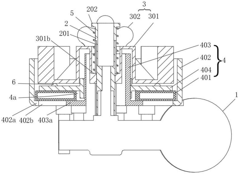
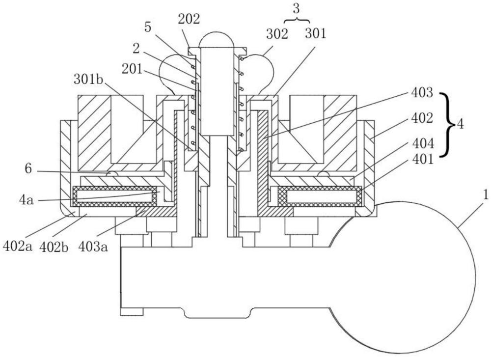
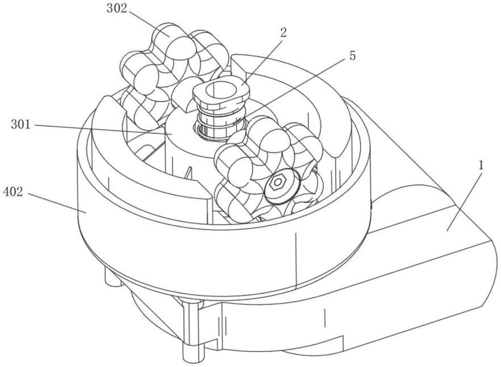
Referring to FIG. 1-5, a massage mechanism is disclosed in this embodiment, comprising a drive source 1, a rotating rod 2, a massage head assembly 3 and an airbag member 4, wherein:
The drive source 1 has an output terminal for the output torque, where the drive source 1 adopts a drive motor, and the output shaft of the drive motor is used for the output of the output torque;
The rotating rod 2 is connected to the output of the driving source 1, specifically, the rotating rod 2 is directly fixed connected with the output shaft of the driving motor, that is, the rotation of the rotating rod 2 is driven by the driving motor;
The massage head assembly 3 comprises a seat 301 and at least one massage head 302 arranged on the seat 301, and the seat 301 is arranged on the rotating rod 2 in such a way that it can rotate synchronously with the rotating rod 2 and can be driven to move along the single degree of freedom in the direction of the axis of the rotating rod 2; Specifically, here the massage head 302 is two symmetrically set, of course, in other embodiments it can be set as other numbers as needed; The structure of the massage head is the same as that of the existing seat mechanical massage structure, which will not be repeated here; When the rotating rod 2 rotates, the massage head 302 can rotate around the rotating rod 2 at the same time, so as to achieve deep massage of the human body;
the airbag member 4, including the airbag body 401, the airbag body 401 is configured to be able to expand or contract in the direction of the rotating rod 2 axis, so as to drive the seat body 301 to move along the direction of the rotating rod 2 axis; It is understandable that the airbag body 401 can be connected with the air source and completed the inflation and deflation of the airbag body 401 by means of air pump control, so as to quickly realize the expansion and contraction of the airbag body 401, and the airbag body 401 generally adopts rubber air bags, etc.;
The massage mechanism provided in the above structure has a good massage effect, which can help improve the comfort evaluation of different drivers and passengers, and at the same time, the structure is simple, which is conducive to reducing production costs. Specifically, the massage head assembly 3 in this massage mechanism can adjust the ejection height position of the massage head 302 under the action of the airbag component 4, so as to adapt to the massage intensity needs of different drivers and passengers, and can more directly and effectively perform deep massage on the muscle groups. It can help improve the comfort evaluation of different drivers and passengers; At the same time, the seat body 301 of the massage head assembly 3 is driven and moved by the airbag component 4, and the airbag can be quickly expanded and contracted by inflating and deflating, which is convenient to control, which is conducive to simplifying the structure, reducing production costs, and is conducive to market promotion; In addition, in specific application, the specific pressure value can be detected by setting up a pressure sensor at the end of the massage head 302, and then adjusting the position of the massage head 302 by actively controlling the inflation inside the airbag, so as to meet the needs of different drivers and passengers for the use of massage strength; In addition, the structure has good compactness and small space occupation, which is conducive to the arrangement in the seat body; Reliable structure and good durability.
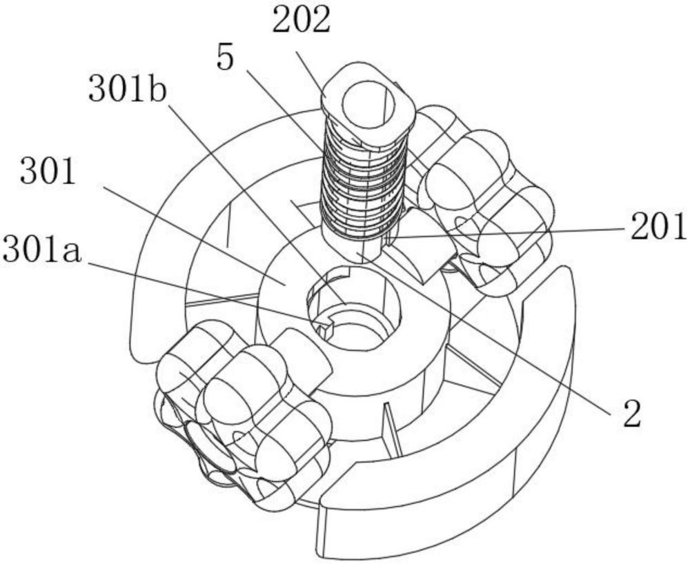
In the present embodiment, a return spring 5 is also included, and the return spring 4 is arranged between the top of the rotating rod 2 and the seat 301, which is used to provide the return force of the seat body 301 when the airbag body 401 is in a contracted state; By setting the return spring 5, when the massage function is not needed, the seat body 301 can automatically retract under the action of the return spring 5 return force, and drive the massage head 302 to retract back, so as not to affect the flatness of the back of the seat and other products, and ensure the comfort of the seat and other products when the massage function is not used; Of course, the return spring 5 itself has a certain buffering performance, which is conducive to further improving the adaptive adjustment function of the ejection position of the massage head 302, so as to further improve the massage effect of the massage mechanism and meet the needs of different drivers and passengers.
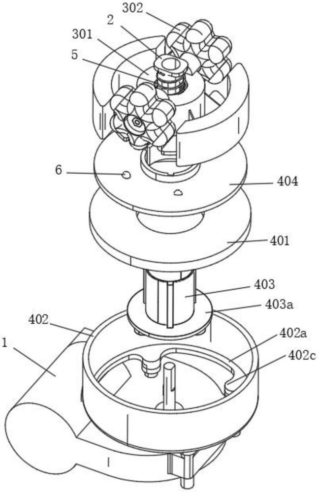
In the present embodiment, the airbag member 4 also comprises a fixed outer guide sleeve 402, a fixed inner guide sleeve 403 and an upper substrate 404 arranged coaxially, the fixed inner guide sleeve 403 and the rotating rod 2 are coaxially arranged, the upper substrate 404 single degree-of-freedom sliding jacket is arranged in a fixed inner guide sleeve 403, and the upper substrate 404, a fixed inner guide sleeve 403 and a fixed outer guide sleeve 402 form a guide space 4a for limiting the expansion or contraction deformation direction of the airbag body 401. the seat body 301 is offset on the top surface of the upper substrate 404 under the action of the return spring 5; It should be noted that the "fixed" in the fixed outer guide sleeve 402 and the fixed inner guide sleeve 403 here means that the fixed external guide sleeve 402 and the fixed inner guide sleeve 403 themselves are fixed in the fixed position; The fixed outer guide sleeve 402 and the fixed inner guide sleeve 403 are expanded or contracted and deformed in the interlayer formed by the two. When the airbag body 401 is inflated and expanded, the upper substrate 404 is pushed outward, and then the seat body 301 is pushed to move, so that the massage head 302 protrudes outward; the "outward" mentioned in this paragraph is the top direction of the rotating rod 2; By setting up the upper substrate 404, the seat 301 can rotate on the upper substrate 404 without directly contacting the airbag body 401, which is conducive to ensuring the durability of the airbag body 401 and ensuring the smooth rotation of the seat 301.
In the present embodiment, a plurality of balls 6 is arranged along the circumferential direction of the rotating rod 2 between the top surface of the upper substrate 404 and the bottom surface of the seat body 301; Specifically, here are multiple ball 6 evenly distributed settings; Ball 6 can be set on the upper substrate 404 or on the seat 301; By setting a ball 6, it is conducive to reducing the friction between the upper substrate 404 and the seat 301, thereby further improving the rotation smoothness of the seat 301 and improving the service life.
In the present embodiment, the lower part of the fixed inner guide sleeve 403 is provided with a radially raised annular support table 403a, the annular support table 403a is fixedly connected with the shell of the drive source 1, and the air bag body 401 jacket is fixed inner guide sleeve 403 and supported on the annular support platform 403a; By arranging the ring support table 403a is conducive to the formation of support for the bottom of the airbag body 401, which is conducive to the fixed connection with the housing of the driving source 1; Specifically, here the housing of the ring support table 403a and the drive source 1 is fixed by screws; The overall structure is simple.
In the present embodiment, the bottom of the inner wall of the fixed outer guide sleeve 402 is provided with a radially inward extension ring boss 402a, and a gap 402b is left between the ring boss 402a and the ring support platform 403a; The annular boss 402a formed by it can be used as the support part of the bottom of the airbag body 401, which is conducive to lightweight design; The gap 402b can also be used as an arrangement channel for the external trachea of the airbag body 401 (the trachea is not shown in the figure).
In the present embodiment, the annular boss 402a is evenly distributed along the circumferential direction and is provided with a plurality of fixed lugs 402c, and the fixed lug 402c is fixedly connected with the housing of the driving source 1; By setting up multiple fixed lugs 402C, it is conducive to the fixed connection of the housing with the drive source 1 and ensure the reliability of the connection.
In the present embodiment, the outer wall of the rotating rod 2 is provided with a guide groove 201 arranged along its own length, the seat body 301 coaxial sliding jacket is arranged on the rotating rod 2, and the guide key 301a is provided on the hole wall of the seat 301 sliding and matching with the guide groove 201; Specifically, here the guide groove 201 is two groups symmetrically arranged on the rotating rod 2; The structure is simple and reliable, which is conducive to ensuring the smooth and reliable sliding of the seat body 301 on the rotating rod 2.
In the present embodiment, the top of the rotating rod 2 is provided with a ring upper limit table 202, the hole wall of the seat body 301 is provided with a ring lower limit table 301b, and the return spring 5 jacket is arranged on the rotating rod 2; And one end of the return spring 2 is offset on the annular upper limit table 202, and the other end is offset on the annular lower limit stage 301b; In this structural design, the return spring 5 has good compactness and good operating reliability.
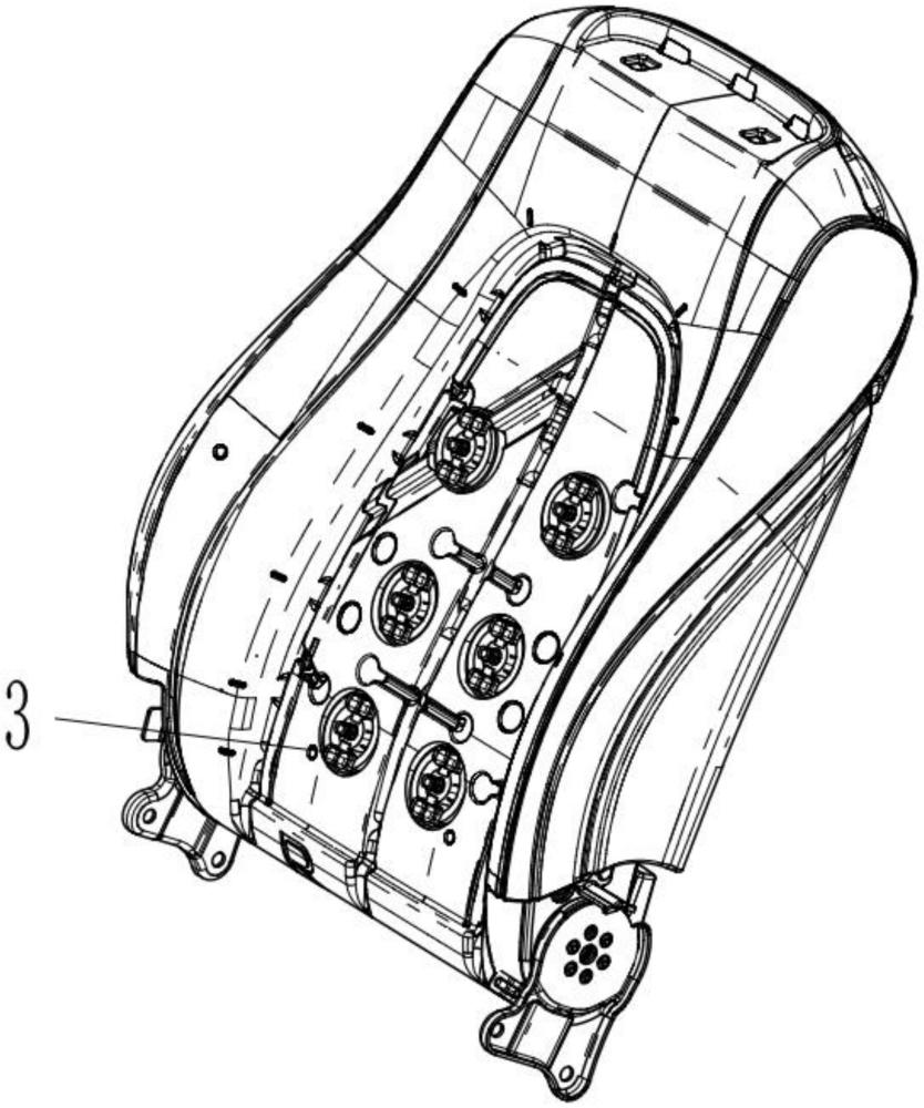
A car seat is also disclosed in the present embodiment, comprising a plurality of groups of massage mechanisms as described above; See Figure 5, specifically, here it is set as six groups; When the massage mechanism is specifically arranged, the shell of the driving source of the massage mechanism (generally the drive motor) can be fixed and installed in a suitable position on the internal skeleton of the seat, and the six groups of massage mechanisms are arranged in two columns in three groups; This car seat can achieve a good massage effect, simple structure, and is conducive to reducing production costs.
The specific application of the above-mentioned car seats can be implemented according to the following working principles:
When the occupant leans on the seatback, the start and stop of the air pump can be controlled through the seat controller, and the airbag body 401 can be inflated through the air pipe, pushing the massage assembly 3 forward to do an ejection action, and the return spring 5 is compressed. When the occupant leaves the seatback, the air pump opens the deflation valve, the airbag body 401 deflates, and the return spring 5 recovers under the guidance of the rotating lever 2, pushing the massage assembly 3 to retract. The force of the mechanical massage head can be detected by the pressure sensor pad against which the passenger is leaning on it, so as to achieve it on the program set by the controller. Under the action of the drive motor, the rotating rod 2 is driven to rotate, so as to drive the massage assembly 3 to perform rotational motion. The controller can also control the independent forward and reverse movements of the respective drive motors of multiple sets of massage mechanisms, so as to provide more massage modes and perform deep massage of muscle groups more directly and effectively.
Finally, it is stated that the above embodiments are only used to illustrate the technical solution of the present invention and not to limit it, although the present utility model is described in detail with reference to the better embodiments, ordinary personnel skilled in the field should understand that the technical scheme of the present utility model can be modified or equivalent to replace, without deviating from the purpose and scope of the technical solution of the present utility model, and it should be covered within the scope of the claims of the present model.






 400-4929-0909
 contact@catarc.com.cn

