Technical Field
The invention relates to a device for an electric vehicle, in particular to an electric vehicle movement and its control method.
Background Art
Electric vehicle to vehicle-mounted power source to power, drive wheel motor for forward driving, the environmental impact of the small and is more and more people have a good prospect.
In the field of the electric vehicle, the power source of the electric vehicle and the endurance capacity of the power storage battery has become a bottleneck in the development of electric cars, the power of the electric automobile battery pack comprises lithium battery, lead-acid battery, fuel cell, etc., some electric vehicle also used super capacitor bank as a power source, although they are generally large to be carried by the charge and discharge of electric current, but their endurance capacity is still not sufficient to meet the use, but also, the above-mentioned power source charging inconvenience, further impact on the mileage of the electric vehicle.
Therefore, needs a device increase the electric vehicle mileage, can effectively improve the endurance capacity of the electric vehicle to the power source, but also can effectively recovering braking when the electric energy generated by the power generation of a motor.
Content of the invention
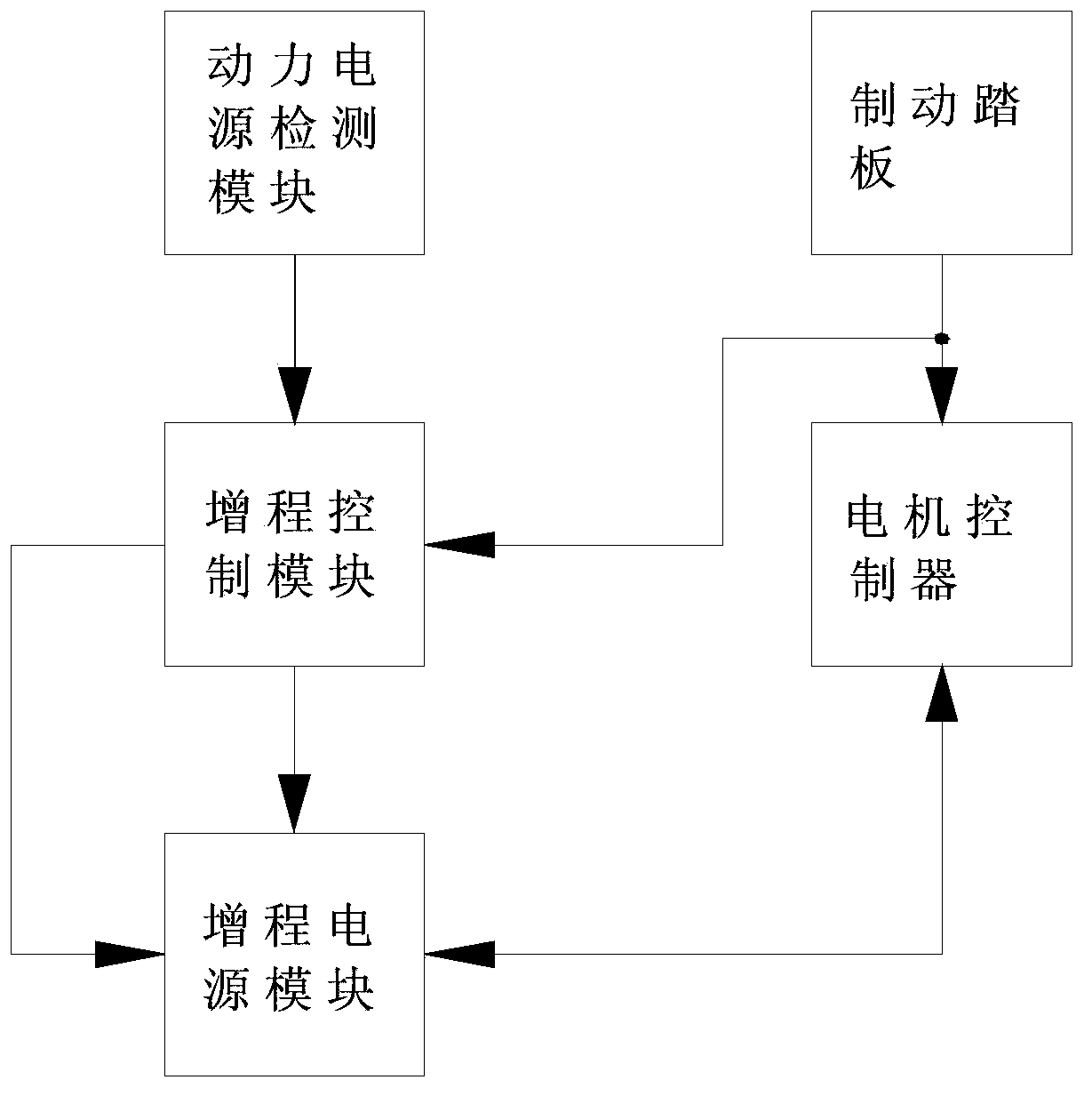
In view of this, the invention provides a movement of motor vehicle, can effectively improve the endurance capacity of the power source of the electric vehicle, but also can effectively recovering braking when the electric energy generated by the power generation of a motor.
The invention provides a movement-electric vehicle, comprising:
Power supply detection module, for collecting the power supply voltage of the power supply and power supply current signal and an output;
Distance increasing power supply module, used for receiving the power supply control signal, when the power supply current or to the power supply voltage reaches the minimum permissible value, distance increasing power supply module to the vehicle power supply, when the electric vehicle brake during braking, used for receiving the electric energy generated by the motor;
Distance increasing control module, is used for receiving the detection module outputs the power supply voltage and a current signal, to the distance increasing the output of power supply module power supply control signal, when the electric vehicle brake during braking, is used for receiving the brake signal and the stroke increasing the output of power supply module feeding control signal, the power supply module receives control stroke increasing the electric energy generated by the motor;
Furthermore, the power supply of the power supply module comprises [...] catalysts, 1st field effect transistor Q1, 2nd diode D2, 3rd resistor R3, 4th resistor R4, 2nd field effect transistor Q2, 3rd diode D3 and a current sensor II;
[...] through the positive pole of the power supply the 3rd resistor R3 and 4th resistor R4 to ground after being connected in series, the 1st of the field effect transistor Q1 of the positive pole of the power supply source is connected to the shafts, the 1st of the field effect transistor Q1 is connected to the drain of the output end of the feedback energy, the 2nd diode D2 is connected to the positive electrode of the field effect transistor 1st Q1 source, 2nd diode D2 is connected to the 1st the negative electrode of the field effect transistor Q1 drain, the 2nd of the field effect transistor Q2 of the negative electrode of the power source is connected to the shafts, 2nd field effect transistor Q2 to ground the drain of the, 3rd diode D3 is connected to the 2nd the positive electrode of the field effect transistor Q2 source, 3rd diode D3 negative ground, the current sensor is connected to the II range increasing the negative pole of the power supply, the power source is a lithium battery [...] ;
Furthermore, the power power supply detection module comprises a 1st diode D1, 1st resistor R1, 2nd resistor R2 and a current sensor I;
The 1st resistor R1 and 2nd resistor R2 in series one end is connected to the power positive electrode of the power source, the other end is grounded, the 1st diode D1 is connected to the positive electrode of the positive pole of the power supply, 1st diode D1 is connected to the 1st the negative electrode of the field effect transistor Q1 of the drain electrode, the current sensor is connected to the I power the negative pole of the power supply;
Furthermore, the control module comprises [...] eight terminal, the 1st stroke increase control module of the terminal A1 is connected to the 1st resistor R1 and 2nd resistor R2 between, 2nd terminal A2 is connected to the 3rd resistor R3 and 4th resistor R4 between, 3rd terminal A3 is used for receiving the current sensor output II of the current signal of the power supply, 4th terminal A4 is connected to the 2nd field effect transistor Q2 gate, 5th terminal A5 is connected to the 1st of the field effect transistor Q1 of the gate, 6th terminal A6 electric vehicle brake pedal for receiving the output of the brake signal, 7th terminal A7 output power display signal, 8th terminal A8 I for receiving the output of the current sensor of the current signal of the power supply;
Furthermore, also includes a display module, the input end of the control module is connected to the sequential 7th terminal A7, for displaying power stroke increasing the power and the power consumption of the power source and the power consumption of the power source feeding power;
Furthermore, the power supply and a power [...] rated voltage of the power supply;
Furthermore, for the single-chip microcomputer of the control module [...] and its corresponding control circuit.
The invention provides a method of controlling vehicle movement, its characteristic is:it comprises following steps:
A power supply detection module current sensor detection I of the supply current of the power supply, the output of the sensor when a current I with a positive analog signal output, a current sensor I of the supply current of the power supply the power to transmit signals to the distance increasing control module;
B distance increasing control module will power the power supply current signal and a power supply with the maximum allowable current value, the power supply when it is lower than the maximum allowed current value or catalysts to the power control module detects the power supply voltage is lower than the lowest allowable voltage value, distance increasing control module to 2nd stroke increase of a power supply module of the field effect transistor Q2 output control signal;
2nd catalysts c of a power supply module of the field effect transistor Q2 gate receiving the distance increasing the control module is turned on after the control signal output, distance increasing a power supply start power supply, when the power supply of the power supply current to return to the normal, distance increasing a control module outputs a control signal and switches off the 2nd of the field effect transistor Q2;
D distance increasing power supply to stop power supply;
Furthermore, step c and step between d e also includes the step, for e the steps of: when the distance increasing control module detects that the stroke increasing the voltage of the power reach the set minimum working voltage value, distance increasing a control module outputs a control signal and switches off the 2nd of the field effect transistor Q2;
Furthermore, also comprises a step f, said step f as: when the distance increasing control module detects that the brake pedal the output of the brake signal, the control module to the 1st stroke increasing the field effect transistor Q1 output control signal, opening 1st field effect transistor Q1, at the same time the brake pedal the controller outputs a control signal to the motor, the motor begins to generate electricity, power stroke increasing the electric energy generated by the receiving motor.
The beneficial effect of the invention is: the invention adopts the distance increasing power supply, so that the running of the electric motor car mileage and not in use at the time of movement provided by the invention is improved compared with the traveling mileage of 50% or more, in the city driving on the road, the brake brake more frequently, the feedback of the motor generated energy can be the traveling mileage of the vehicle increase compared with the original 10% or more, and the power source of the electric vehicle and the distance increasing power supply the large current power supply conditions automatic balancing, so that the electric power of the vehicle performance is notably improved, effectively protect the power supply, preventing the power supply overload use, prolonging the service life of the power supply, and, the circuit of the present invention is simple in structure, good stability, it is easy to realize, the cost is low.
Description of drawings
The embodiment of Figure and with the further description of this invention:
Figure 1 is not of the present invention is access to the electric power system schematic circuit diagram.
Figure 2 is the invention access to the electric power system in the schematic circuit of the.
Figure 3 is in the working process of the present invention sequential power supply equivalent schematic diagram of the power supply.
Figure 4 is in the working course of this invention at the power receiving shafts the equivalence principle of the Figure.
Figure 5 is an electric vehicle of the present invention control flow chart of the movement.
Mode of execution
Figure 1 is not of the present invention is access to the electric power system schematic circuit diagram, Figure 2 is the invention access to the electric power system in the schematic circuit of the, Figure 3 is in the working process of the present invention sequential power supply equivalent schematic diagram of the power supply, Figure 4 is the invention in the working process at the power receiving shafts of the equivalent schematic diagram, Figure 5 is the movement of the electric motor of this invention the control flow chart, shown in the Figure, the invention provides a movement-electric vehicle, comprising: power supply detection module, for collecting the power supply 1 and the power supply voltage of the power supply current signal and output; distance increasing power supply module, used for receiving the power supply control signal, when the power supply 1 a power supply current or to the power supply voltage reaches the minimum permissible value, distance increasing power supply module to the vehicle power supply, when the electric vehicle brake during braking, for receiving motor 9 the electric energy generated by the; distance increasing control module, is used for receiving the detection module outputs the power supply voltage and a current signal, to the distance increasing the output of power supply module power supply control signal, when the electric vehicle brake during braking, is used for receiving the brake signal and the stroke increasing the output of power supply module feeding control signal, the control distance increasing power supply module receives motor 9 to generate electric energy; this invention adopts the distance increasing power supply, so that the mileage of the electric vehicle of the present invention and not in use at the time of movement provided by the improved mileage compared with 50% or more, in the city driving on the road, the brake brake more frequently, the feedback of the motor generated energy can be the traveling mileage of the vehicle increase compared with the original 10% or more, and the power source of the electric vehicle and the distance increasing power supply the large current power supply conditions automatic balancing, so that the electric power of the vehicle performance is notably improved, effectively protect the power supply, preventing the power supply overload use, prolonging the service life of the power supply, and, the circuit of the present invention is simple in structure, good stability, it is easy to realize, the cost is low.
In this embodiment, the distance increasing the power supply module comprises distance increasing power supply 4, 1st field effect transistor Q1, 2nd diode D2, 3rd resistor R3, 4th resistor R4, 2nd field effect transistor Q2, 3rd diode D3 and a current sensor II 3;
The [...] power supply 4 through the positive pole of the 3rd resistor R3 and 4th resistor R4 to ground after being connected in series, the 1st of the field effect transistor Q1 of the positive pole of the power supply source is connected to the shafts, the 1st of the field effect transistor Q1 is connected to the drain of the output end of the feedback energy, as shown in Figure 2, 1st field effect transistor Q1 is connected to the drain of the motor controller 6 of the terminal B1, the motor controller 6 of the terminal B1 in the motor power generation is used as the distance increasing power supply 4 feedback electric energy output, when the power-supply shafts 1 and 4 to supply, terminal B1 as an electric motor 9 the electric energy input end, braking the motor 9 through the motor controller of the electric energy generated by the 6 terminal B1 through the 1st after the field effect transistor Q1 back to the distance increasing power supply 4 in. The 2nd diode D2 is connected to the positive electrode of the field effect transistor 1st Q1 source, 2nd diode D2 is connected to the 1st the negative electrode of the field effect transistor Q1 drain, the 2nd of the field effect transistor Q2 is connected to the stroke increasing the source electrode of the power supply 4 of the negative electrode, 2nd field effect transistor Q2 to ground the drain of the, 3rd diode D3 is connected to the 2nd the positive electrode of the field effect transistor Q2 source, 3rd diode D3 negative ground, the current sensor II 3 is connected with the distance increasing power supply 4 of the negative electrode, the power supply [...] 4 for the lithium battery, the distance increasing power supply 4 and the power supply 1 is equal to the rated voltage of the; in the power supply 1 of the power supply current or to the power supply voltage is lower than the lowest allowable voltage value, the power supply module [...] to the external power supply, can effectively protect the power supply 1, but also effectively prolonging the mileage of the electric vehicle, the 2nd diode D2 and 3rd diode D3 to large current can pass through the low pressure drop of the diode.
In this embodiment, the power power supply detection module comprises a 1st diode D1, 1st resistor R1, 2nd resistor R2 and a current sensor I 2;
The 1st resistor R1 and 2nd resistor R2 in series one end is connected to the power supply 1 of the positive electrode, while the other end thereof is grounded, the 1st diode D1 is connected to the positive pole of the power supply 1 of the positive electrode, 1st diode D1 is connected to the 1st the negative electrode of the field effect transistor Q1 drain, 1st diode D1 when the distance increasing power supply for preventing 4 power supply or distance increasing power supply 4 accept feed the accepts the electric energy from the power supply, the current sensor I 2 is connected to the power supply 1 of the cathode; the power power supply detection module can be real-time detection of the power supply 1 and the power supply current of the power supply 1 value is transmitted to the stroke increasing the voltage of the control module, so as to control the distance increasing power supply module to supply power.
In this embodiment, the distance increasing control module 5 for the single-chip microcomputer of the control circuit and its corresponding, single-chip microcomputer and the control circuit for the prior art, in this do not repeat; the [...] control module 5 includes eight terminals, said distance increasing control module 5 1st terminal of A1 is connected to the 1st resistor R1 and 2nd resistor R2 between, 2nd terminal A2 is connected to the 3rd resistor R3 and 4th resistor R4 between, 3rd terminal A3 is used for receiving the current sensor II 3 output of the power supply 4 of the current signal, 4th terminal A4 is connected to the 2nd field effect transistor Q2 gate, 5th terminal A5 is connected to the 1st of the field effect transistor Q1 of the gate, 6th terminal A6 is used for receiving the electric vehicle brake pedal 7 output the brake signal, in the Figure 2 in, 6th terminal A6 is connected to the brake pedal 7 the output of the brake signal, and the brake pedal 7 of the brake signal output also is connected to the motor controller 6 of the brake signal receiving end, that is, terminal B3, when the brake pedal 7 when a braking signal is output, stroke increase control module 5 outputs a control signal to make the 1st of the field effect transistor Q1 open, at the same time motor controller 6 so that the motor 9 power generation, by the motor controller 6 and electric energy output end of the (terminal B1) is transmitted to the distance increasing power supply module, so as to complete the recovery of electric energy, brake controller 6 of terminal B3 ground; 7th terminal A7 output power display signal, 8th terminal A8 I 2 for receiving the current sensor output of the power supply 1 of the current signal;
In this embodiment, the electric vehicle distance increasing the controller also includes a display panel, the input end of the control module is connected to the sequential 7th terminal A7, for displaying power supply 1 and the power supply 4 of power; the display board 8 can display the power supply 1 and the power supply 4 power consumption, the feedback power, at the same time the display of them, whether under-voltage, the distance increasing controller 5 to display control; when the current sensor II 3 output is a positive value, the display panel 8 display "+XKW", wherein the "+" for the power consumption is, X is a power value, the power units KW, when the current sensor II 3 output to a negative value, the display panel 8 is displayed as "-XKW", wherein "-" in order to feedback the electric energy.
Figure 3 is the equivalent circuit schematic diagram of power supply of the invention, when the electric vehicle at the time of an initial driving, the power supply 1 and the distance increasing power supply 4 supply power at the same time, when the distance increasing power supply 4 the power consumption of the rated capacity of the 10% of the, power stroke increasing the control module controls sequential 4 stop power supply, the feedback of braking when the electric energy supply storage space; when the power supply 1 in the over-current or power supply voltage is too low, distance increasing controller 5 control distance increasing power supply 4 to the power supply, wherein the R5 to 2nd field effect transistor Q2 is turned on the equivalent resistance, I1 to power supply 1 a power supply current, I2 is a distance increasing power supply 4 of the power supply current, motor controller 6 to supply current of the obtained I= I1 + I2.
Figure 4 is in the working course of this invention at the power receiving shafts the equivalence principle of the Figure, that is, the motor of this invention the feed of the equivalent schematic diagram, wherein R6 is a 1st field effect transistor Q1 when the equivalent resistance of the turned on, the motor 9 through the motor controller of the electric energy generated by the 6 input to the distance increasing power supply 4 in.
The invention provides a method of controlling vehicle movement, its characteristic is:it comprises following steps:
A power supply detection module current sensor detection I of the supply current of the power supply, the output of the sensor when a current I with a positive analog signal output, a current sensor I of the supply current of the power supply the power to transmit signals to the distance increasing control module;
B distance increasing control module will power the power supply current signal and a power supply with the maximum allowable current value, the power supply when it is lower than the maximum allowed current value or catalysts to the power control module detects the power supply voltage is lower than the lowest allowable voltage value, distance increasing control module to 2nd stroke increase of a power supply module of the field effect transistor Q2 output control signal;
2nd catalysts c of a power supply module of the field effect transistor Q2 gate receiving the distance increasing the control module is turned on after the control signal output, distance increasing a power supply start power supply, when the power supply of the power supply current to return to the normal, distance increasing a control module outputs a control signal and switches off the 2nd of the field effect transistor Q2;
D distance increasing power supply to stop power supply;
In this embodiment, step c and step between d e also includes the step, for e the steps of: when the distance increasing control module detects that the stroke increasing the voltage of the power reach the set minimum working voltage value, distance increasing a control module outputs a control signal and switches off the 2nd of the field effect transistor Q2;
In this embodiment, electric vehicle movement control method also includes the step of f, said step f as: when the distance increasing control module detects that the brake pedal the output of the brake signal, the control module to the 1st stroke increasing the field effect transistor Q1 output control signal, opening 1st field effect transistor Q1, at the same time the brake pedal the controller outputs a control signal to the motor, the motor begins to generate electricity, power stroke increasing the electric energy generated by the receiving motor, so as to complete the recovery of the electric energy.
In this embodiment, power supply 1 and the distance increasing power supply 4 is the minimum allowed voltage value set according to different of the battery pack, generally according to the production factory calibration to set the minimum allowed voltage value.
Finally note that, the above-mentioned embodiment in order to illustrate the technical scheme of the invention and non-limiting, although with reference to the preferred embodiments of a detailed explanation of the invention, the ordinary technical personnel in this field should be understood, the technical scheme of this invention for equivalent modification or replacement, and can not be separated from the technical scheme of the invention the purpose and scope of, its should be covered in this invention, the scope of the claim.
Range extender for electric vehicle and control method of range extender




 400-4929-0909
 contact@catarc.com.cn

