Torsion beam high-frequency quenching method capable of eliminating abnormal soundTechnical Field
The invention relates to the technical field of torsion beam quenching processing, in particular to a torsion beam high-frequency quenching method capable of eliminating abnormal sound.
Background
For the automobile torsion beam structure shown in fig. 1, two ends of the automobile torsion beam structure are hollow tube bodies with regular shapes, the middle part of the automobile torsion beam structure is gradually deformed to form a V-shaped structure shown in fig. 2, and a region where the tube wall is bent and attached has no gap; in the prior art, the heat treatment method of the torsion beam can refer to the heat treatment method of the high-strength thermal imaging torsion beam for the automobile disclosed in the invention patent application with the publication number of CN108504985A, and comprises pretreatment, carburization, quenching, cleaning, tempering and the like, wherein in the carburization, carbon-containing gas is introduced into non-oxidative protective gas to increase the carbon content of the torsion beam so as to improve the strength of the torsion beam; in the quenching treatment, in order to prevent the torsion beam from decarbonizing, the torsion beam is immersed in an oil bath for cooling, but the quenching method needs longer time, the material consumption of the oil bath is larger, and the heat treatment cost is higher.
In the prior art, a torsion beam is treated in a high-frequency quenching mode, firstly, a part is instantly heated to 900 ℃ by using an induction coil, then, the part is immediately sprayed and cooled, and the whole part is heated and then cooled, so that the deformation of a product is large, the size of the molded surface of the product is very unstable, the pipe wall of a V-shaped area can deform to generate a gap (as shown in figure 3), the two inner walls of the V-shaped area must be attached within the range of 600mm width in the middle of the design requirement, otherwise, abnormal sound can be generated due to the friction of the inner walls caused by the gap in the loading and using process of the torsion beam; in addition, when high-frequency quenching treatment is carried out, oxidation and decarburization can occur on the surface of the torsion beam, and a large amount of oxide skin exists on the inner surface and the outer surface. The outer surface oxide skin can be eliminated through shot blasting, but the inner surface oxide skin in the V-shaped area cannot be eliminated, and the oxide skin can remain in the gap between the inner walls of the two products in the V-shaped area. After the torsion beam is welded and loaded, because the two inner walls of the V-shaped area can slide and deform relatively, oxide skin at the residual gap can rub the two inner walls, and abnormal sound can be generated.
Disclosure of Invention
The invention aims to provide a high-frequency quenching method capable of preventing the quenching deformation and the surface oxidation of a torsion beam.
The invention solves the technical problems through the following technical scheme: a torsion beam high-frequency quenching method capable of eliminating abnormal sound analyzes stress borne by each part of a torsion beam under real road conditions through simulation and simulation, and compared with the strength of the torsion beam under an unhardened state, quenching treatment is carried out on regions which are not jointed at two ends and have high bearing stress, and quenching treatment is not carried out on regions which are jointed at low bearing stress.
According to the invention, the real stress condition of the torsion beam is analyzed through simulation, so that the bearing capacity requirements of each part of the torsion beam are determined, the two ends of the torsion beam which are not jointed are only subjected to heat treatment quenching, and the V-shaped area formed by jointing the middle part is not subjected to heat treatment, so that the jointing area is prevented from deforming in the heat treatment, the generation of gaps is avoided, and abnormal sound caused by friction due to the gaps is avoided.
Preferably, the simulation method comprises: and importing the torsion beam digital model into CAE software, loading the real road condition of the torsion beam, acquiring the stress condition borne by each part of the torsion beam, and determining the high stress area of the torsion beam.
Preferably, the range of the attaching area and the range of the non-attaching area of the torsion beam are obtained, and the range of the quenching area of the torsion beam is determined, wherein the range of the quenching area at least covers the high stress area of the torsion beam.
Preferably, the high stress area is within a range of 100-250mm away from the two ports of the torsion beam, the non-bonding area is within a range of 300mm inward of the two ports, and the quenching area is within a range of 50-350mm inward of the two ports.
Preferably, the method further comprises the step of inserting the positioning chucks into two ends of the torsion beam for fixing, and the fixed torsion beam is subjected to quenching treatment in the quenching area in quenching equipment.
Preferably, the positioning chuck comprises a boss, the boss is in splicing fit with the port of the torsion beam, a vent hole is formed in the boss of the positioning chuck below the boss, and the vent hole is connected with a protective air source.
Preferably, the protective gas source is nitrogen or argon.
Preferably, four vent holes are formed in a boss of the positioning chuck below the positioning chuck, each vent hole is connected with one gas distribution pipe, the four gas distribution pipes are connected to the main gas pipe, and a digital display flow control valve is arranged on the main gas pipe.
Preferably, the gas flow Q on the main gas pipe satisfies the condition that Q is more than or equal to 1.2Q1;
Wherein Q is1The calculation method is that the gas leakage amount is calculated as follows:
Q1=V*A
![]()
in the above formula, V is the average flow velocity, a is the cross-sectional area of the torsion beam port, and P is 0.6 × 10⁶MPa, which is the gas pressure,![]() is the air density, T is the ambient temperature in degrees Celsius; then
is the air density, T is the ambient temperature in degrees Celsius; then
![]()
Preferably, after the positioning chuck fixes the torsion beam, protective gas is filled through the vent holes in the boss, then the quenching equipment carries out heat treatment on the quenching area of the torsion beam, and after quenching is finished, gas supply is stopped.
The torsion beam high-frequency quenching method capable of eliminating abnormal sound provided by the invention has the advantages that: the real stress condition of the torsion beam is analyzed through simulation, so that the bearing capacity requirements of all parts of the torsion beam are determined, the two ends of the torsion beam which are not jointed are only subjected to heat treatment quenching, and a V-shaped area formed by jointing the middle part is not subjected to heat treatment, so that the jointing area is prevented from deforming in the heat treatment, the generation of gaps is avoided, and abnormal sound caused by friction due to the gaps is avoided. When the torsion beam is subjected to heat treatment, the torsion beam is prevented from being oxidized at high temperature by filling the protective gas into the torsion beam, so that abnormal sound caused by an oxide layer is avoided, and the problem of abnormal sound of a vehicle is thoroughly solved. Meanwhile, a calculation formula of the using amount of the protective gas is provided, so that the original gas in the torsion beam can be discharged, and the torsion beam is prevented from being oxidized.
Drawings
Fig. 1 is a schematic view of a torsion beam high-frequency quenching method capable of eliminating abnormal sound according to an embodiment of the present invention;
FIG. 2 is a schematic view of a V-shaped section of a torsion beam according to an embodiment of the present invention;
FIG. 3 is a schematic view of a torsion beam V-shaped zone quenched for deformation according to an embodiment of the present invention;
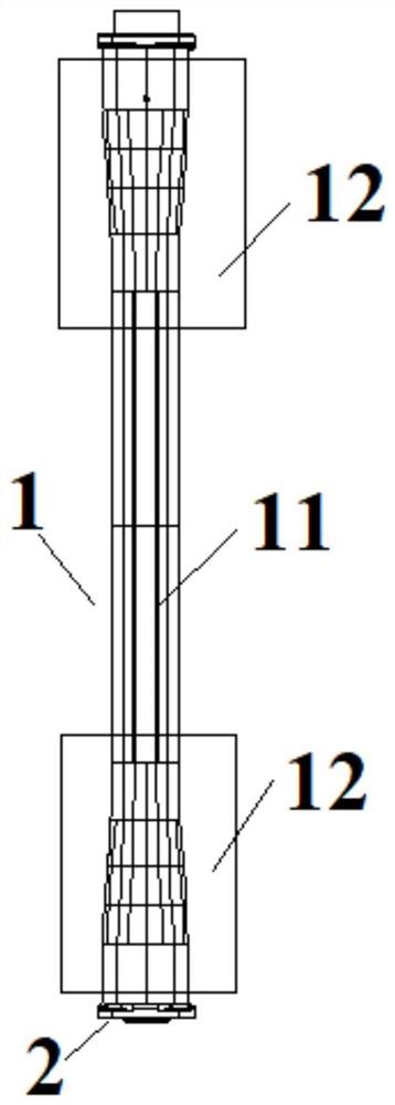
fig. 4 is a schematic diagram illustrating a division of a torsion beam region of a torsion beam high-frequency quenching method capable of eliminating abnormal sound according to an embodiment of the present invention;
fig. 5 is a schematic view of a positioning chuck of a torsion beam high-frequency quenching method capable of eliminating abnormal noise according to an embodiment of the present invention.
Detailed Description
To make the objects, technical solutions and advantages of the present invention more apparent, the technical solutions of the present invention are described below in detail and completely with reference to the accompanying drawings, and it is apparent that the described embodiments are some, but not all embodiments of the present invention. All other embodiments, which can be derived by a person skilled in the art from the embodiments given herein without making any creative effort, shall fall within the protection scope of the present invention.
The embodiment provides a torsion beam high-frequency quenching method capable of eliminating abnormal sound, which includes analyzing stress borne by each part of the torsion beam 1 under real road conditions through simulation, comparing the stress with the strength of the torsion beam under an unquenched state, referring to fig. 4, according to analysis, regions, which are not attached to two ends of the torsion beam 1, bear larger stress, and should be quenched, that is, a quenching region 12, and a V-shaped attaching region, which has lower stress at the middle part, does not need quenching.
The real stress condition of the torsion beam is analyzed through simulation, so that the bearing capacity requirements of all parts of the torsion beam are determined, the two ends of the torsion beam which are not attached are only subjected to heat treatment quenching, and the V-shaped area 11 formed by attaching the middle of the torsion beam is not subjected to heat treatment, so that the attachment area is prevented from deforming in the heat treatment, the generation of gaps is avoided, and abnormal sound caused by friction due to the gaps is avoided.
The simulation method comprises the following steps: the torsion beam digifax is led into CAE software, real road conditions of the torsion beam 1 are loaded through grid pretreatment, stress conditions borne by each part of the torsion beam 1 are obtained, and a high stress area of the torsion beam 1 is determined.
The areas of the attachment area and the non-attachment area of the torsion beam 1 are then obtained, and the area of the quenching area 12 is then determined, wherein the quenching area 12 should at least be able to cover the high stress area of the torsion beam 1. In this embodiment, the non-bonding area of the torsion beam 1 is within a range that two ports are inward 300mm, the finally determined quenching area 12 is within a range that two ports are inward 50-350mm, the specific size needs to be determined according to the structure of the torsion beam 1, the quenching area 12 is ensured to cover a high-stress area, and meanwhile, the quenching area 12 cannot intersect with the bonding area of the V-shaped area 11 in the torsion beam 1.
Referring to fig. 4 again, the high-frequency quenching method further includes a step of inserting the positioning chucks 2 into both ends of the torsion beam 1 for fixing, and the fixed torsion beam 1 performs a quenching process on the quenching area 12 in a quenching apparatus, wherein the quenching apparatus is an existing heat treatment apparatus.
Referring to fig. 5, the positioning clamp 2 includes a boss 21, the boss 21 is inserted into and matched with a port of the torsion beam 1, so as to fix the inner side of the torsion beam 1, and a vent hole (not shown) is provided on the boss 21 of the positioning clamp 2 located below, and the vent hole is connected with a protective air source. When the thermal treatment is carried out, the protective gas is filled into the torsion beam 1, so that the torsion beam is prevented from being oxidized at high temperature, abnormal sound caused by an oxide layer is avoided, and the problem of abnormal sound of a vehicle is thoroughly solved.
Specifically, the protective gas source is nitrogen or argon, or other inert gases can be used.
The boss 21 of the positioning chuck 2 below is provided with four vent holes, each vent hole is connected with a gas distribution pipe 22, the four gas distribution pipes 22 are connected to a main gas pipe 23, and the main gas pipe 23 is provided with a digital display flow control valve 24. After the positioning chuck 2 fixes the torsion beam 1, protective gas is filled in through the vent holes on the boss 21, then quenching equipment carries out heat treatment on the quenching area 12 of the torsion beam 1, after quenching is finished, gas supply is stopped, the torsion beam 1 is taken down, and the gas flow Q used on the main gas pipe 23 meets the following formula:
Q≥1.2Q1
wherein Q is1The calculation method is that the gas leakage amount is calculated as follows:
Q1=V*A
![]()
in the above formula, V is the average flow velocity, a is the cross-sectional area of the torsion beam port, and P is 0.6 × 10⁶MPa, which is the gas pressure,![]() is the air density, T is the ambient temperature in degrees Celsius; then
is the air density, T is the ambient temperature in degrees Celsius; then
![]()
The above examples are only intended to illustrate the technical solution of the present invention, but not to limit it; although the present invention has been described in detail with reference to the foregoing embodiments, it will be understood by those of ordinary skill in the art that: the technical solutions described in the foregoing embodiments may still be modified, or some technical features may be equivalently replaced; and such modifications or substitutions do not depart from the spirit and scope of the corresponding technical solutions of the embodiments of the present invention.


 400-4929-0909
 contact@catarc.com.cn

