Summary of the utility model
Based on this, a non-low-tear skin component and vehicle are provided to address the issue in the prior art where unattenuated skin is easily misused.
On one hand, this utility model provides a non-low-tear skin assembly, which is used to wrap interior parts and crack during bursting to open the airbag. The skin assembly includes:
a first epidermis, the first epidermis includes a first mating edge, the first mating edge is located at the edge of the first epidermis;
a second skin, which includes a second mating edge, which is located at the edge of the second skin. The first mating edge corresponds to the second mating edge, and the first skin and the second skin are connected by the connection between the first and second mating edges;
The unweakened indicator part or weakened part is provided at the first mating edge and protrudes from the first mating edge; The weakening part is located on the first epidermis, which is used to indicate that the first epidermis has undergone weakening treatment;
When the first epidermis is in the unweakened state, an unweakened indicator is connected to the first mating edge; When the first epidermis is in a weakened state, there is a weakened part on it.
Based on the above technical solution, the utility model can also be improved as follows.
In one embodiment, the first skin further includes a first positioning portion, which is arranged along the first mating edge;
The second epidermis also includes a second positioning portion, which is arranged along the second mating edge. The first positioning position corresponds to the second positioning position and is used for positioning when connecting the first and second epidermals.
In one implementation, the first positioning unit and the second positioning unit form at least two one-to-one corresponding positioning groups.
In one embodiment, the first positioning part includes multiple first notches formed along the length direction of the first mating edge;
The second positioning part includes multiple second notches formed along the length direction of the second mating edge;
Multiple first and second notch settings correspond one-to-one.
In one implementation, multiple first notches are spaced evenly, and multiple second notches are also spaced evenly.
In one implementation, both the first notch and the second notch are V-shaped notches.
In one implementation, the unattenuated indicator is sheet-shaped and arranged in the middle of two adjacent first notches.
In one implementation, the weakening part is located in the middle region of the first epidermis and has an I-shaped structure.
In one implementation, the first and second mating edges are linear edges of the same length.
On the other hand, this utility model also provides a vehicle comprising a non-low-tear skin component, as well as interior parts that are wrapped around the outer periphery of the interior parts.
The beneficial effect of this utility model is: by providing a prominent unweakened indicator to indicate that the first epidermis has not undergone weakening treatment, it is possible to distinguish whether weakening treatment has been performed based on the external structure of the first epidermis, thereby avoiding mixing unweakened epidermis with the other product; Additionally, the unweakened indicator is set at the first mating edge and protrudes from the first mating edge. Since the first and second epiderms are connected via the first and second mating edges, the unweakened indicator is set at the connecting edge of the two epidermis, allowing timely detection of the presence of an unweakened indicator unit when connecting the first and second epidermis, making the unweakened indicator more obvious and less likely to be overlooked; Correspondingly, if there is an unattenuated indicator part when connecting the first and second epiderms, interference between the first and second mating edges will occur, allowing the first epiderm used to be immediately determined to be unweakened and misused; In summary, this solution can effectively improve the error prevention effect of epidermis components and avoid mixing unweakened and already weakened epidermis.
Specific embodiments
To make the objectives, technical solutions, and advantages of this application clearer and clearer, the following provides a further detailed explanation of this application in conjunction with the drawings and embodiments. It should be understood that the specific embodiments described here are only for interpretation of this application and are not intended to limit it. It should be noted that the diagrams provided in this embodiment are only for illustration purposes to illustrate the basic concept of this utility model. Therefore, the schematics only show components related to the utility model rather than the number, shape, and size of components in the actual implementation. The shape, quantity, and proportion of each component in the actual implementation may be changed at will, and the layout of the components may be more complex.
The structure, proportions, sizes, etc. shown in the drawings attached to this specification are provided solely to accompany the content disclosed in the specification and are intended for those familiar with the technology to understand and read. They are not intended to limit the conditions that can be implemented by this utility model. Therefore, they have no substantive technical significance. Any structural modifications, changes in proportional relationships, or size adjustments, as long as they do not affect the effects produced or the objectives achievable by this utility model, shall still fall within the scope covered by the technical content disclosed herein.
In the event of a collision, the airbag must instantly inflate and deploy to provide cushioning protection for the occupants; The weakening of interior parts aims to reduce resistance when deploying the airbag, ensuring it can deploy promptly along the predetermined trajectory; If the interior parts are not attenuated, the airbag may tear it into pieces when deployed, and these fragments can cause secondary injury to occupants when flying at high speed.
Common weakening treatments include: pre-cutting weakening lines, designing hidden weak lines in airbag coverage areas (such as the center of the steering wheel or dashboard cover), Usually thin-walled structures or laser-cut microgrooves below 0.5mm, these weakening lines rupture preferentially when airbag inflation, forming regular openings; molded weakening processes use molds to emboss shallow grooves or textures on the surface of interior parts, forming preset rupture paths; layered materials and composite structures: some interior parts use multilayer composite materials, with the outer layer being decorative hard material and the inner layer being a low-strength support layer.
In the prior art, during production, the skin assembly contains multiple skins. The skin is first weakened, then the multiple skins are connected together and wrapped around the interior parts; For non-low-tear epilepsy, the visual difference between weakened and untreated skins is not obvious. Therefore, during production, it is easy to mix and connect the under-treated skin and cover interior parts, which can easily cause safety accidents where the airbag cannot deploy. To better distinguish between epidermis that has undergone weakening and that has not been weakened, and to avoid mixing, the following solution is provided.
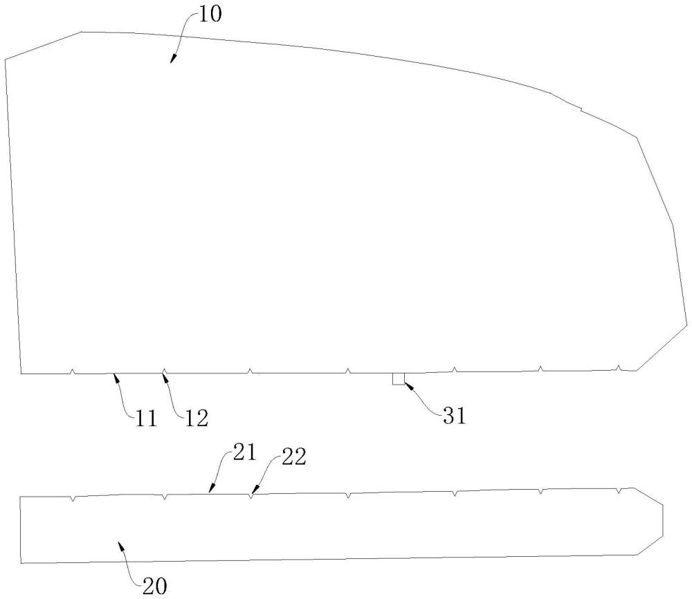
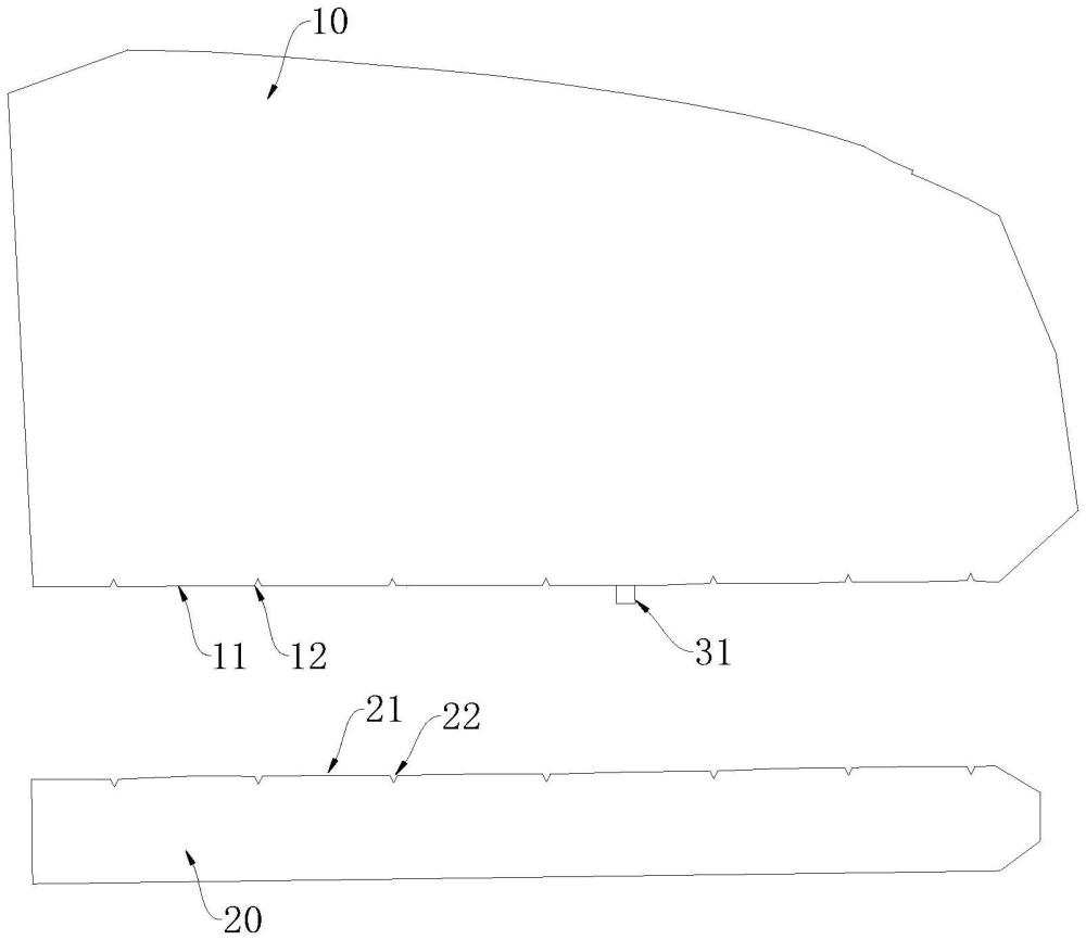
A non-low-tear skin component, see Figures 1 and 2. The skin assembly is used to cover interior parts and split open during bursting to open the airbag. The skin assembly includes a first skin 10 and a second skin 20. The skin assembly further includes an unweakened indicator part 31 or a weakened part 32. The first skin 10 includes a first mating edge 11, which is located at the edge of the first skin 10; The second skin 20 includes a second mating edge 21, which is located at the edge of the second epidermishes 20. The first mating edge 11 corresponds to the second mating edge 21, and the first and second coding edges 10 are connected by the connection between the first mating edge 11 and the second mating edge 21; The unweakened indicator part 31 is provided at the first mating edge 11 and protrudes from the first mating edge 11; The weakening part 32 is located on the first epidermis 10 and is used to characterize that the first epidermis 10 has undergone weakening treatment; When the first epidermis 10 is in the unweakened state, an unweakened indicator part 31 is connected to the first mating edge 11; When the first epidermis 10 is in a weakened state, the first epidermis 10 has a weakened part 32.
Using this scheme, referring to Figures 1 and 2, a prominent unweakened indicator 31 is provided to indicate that the first epidermis 10 has not undergone weakening treatment, allowing identification of weakening treatment from the surface structure of the first epidermis 10 and avoiding mixing unweakened epidermis cases; Additionally, the unweakened indicator part 31 is arranged at the first mating edge 11 and protrudes from the first mating edge 11. Since the first and second epiderms 20 are connected via the first mating edge 11 and the second mating edge 21, the unweakened indicator part 31 is arranged at the connecting edge of the two skins, allowing timely detection of the presence of the unweakened indicator part 31 when connecting the first and second skins, making the unweakened indicator part 31 more obvious and less likely to be overlooked; Correspondingly, if the first skin 10 and second skin 20 are connected to the unweakened indicator part 31, interference will occur between the first and second mating edges 11 and 21, allowing the first skin 10 to be immediately determined to be unweakened and misused; In summary, this solution can effectively improve the error prevention effect of epidermis components and avoid mixing unweakened and already weakened epidermis.
In the embodiment, referring to Figures 1 and 2, during production, when the first epidermis 10 is in an unweakened state, there is a protruding unweakened indicator part 31 on the first mating edge 11 of the first epidermis 10. When the first epidermis 10 is weakened, the unweakened indicator part 31 is correspondingly removed. Therefore, when the first epidermis 10 is in a weakened state, there is a weakened part 32 on the first epidermis 10 and no unweakened indicator part 31.
In the embodiment, because
In some embodiments, referring to Figures 1 and 2, the first skin 10 further includes a first positioning portion, which is arranged along the first mating edge 11; The second skin 20 further includes a second positioning portion, which is arranged along the second mating edge 21. The first positioning position corresponds to the second positioning position and is used for positioning when connecting the first skin 10 and the second skin 20. In this way, a first positioning section and a second positioning part are arranged to position the first skin 10 and second skin 20 during connection, so that the first skin 10 and second skin 20 are connected according to preset positions, ensuring accurate positioning during connection.
In some embodiments, referring to Figures 1 and 2, the first and second positioning parts form at least two one-to-one corresponding positioning groups. Thus, the first and second positioning sections correspond to each other's structures, such as positioning holes or notches, and the corresponding first and second positioning sections need to be arranged and placed to form a one-to-one positioning group. At least two positioning groups can achieve accurate positioning of the relative positions of the first epidermis 10 and the second epidermis 20.
In some embodiments, referring to Figures 1 and 2, the first positioning part includes multiple first notches 12 formed along the length direction of the first mating edge 11; The second positioning part includes multiple second notches 22 formed along the length direction of the second mating edge 21; Multiple first notch 12 and multiple second notch 22 are set one-to-one. In this way, by setting multiple first notches 12 and multiple second notches 22 respectively, positioning can be done by placing the corresponding first and second notches 12 when positioning the first and second mating edges 11 and 21, resulting in multiple first and second notch 22 positions.
In the embodiments, referring to Figures 1 and 2, the number of first notch 12 and second notch 22 can each be at least two, such as setting one to three first notch 12 and three second notch 22, or setting one to seven first notch 12 and seven second notch 22, etc.
In some embodiments, referring to Figures 1 and 2, the multiple first notches 12 are arranged at equal intervals, and the multiple second notches 22 are also arranged at equal intervals. In this way, the first notch 12 is evenly spaced, and the second notch 22 is also evenly spaced, facilitating the opening of the first and second notch 22 on the first and second mating edges 11 and 21 respectively, reducing the machining cost of notch.
In some embodiments, as shown in Figures 1 and 2, both the first notch 12 and the second notch 22 are V-shaped notches. In this way, the notch in the V-shape is convenient. The top opening end of the V-shape is located on the first joining edge 11 and the second joining edge 21, and the bottom tip of the V-shaped shape is set facing away from the first and second joining edges 11 and 21. Therefore, when positioning, only the top opening ends of at least two sets of corresponding first and second notches 12 of the two V-shaped shapes are set to fit each other against each other, allowing positioning of the first and second joining edges 11 and 21. This is to achieve positioning when connecting the first skin 10 and the second skin 20.
In some embodiments, referring to Figures 1 and 2, the unattenuated indicator part 31 is plate-shaped and arranged in the middle of two adjacent first notches 12. Thus, the position of the unweakened indicator part 31 requires other structures corresponding to the normal connection of the first skin 10, so the unweakened indicator part 31 is set in the middle of two adjacent first notches 12 to avoid the influence of the unweakened indicator part 31 on the opening of the first notch 12.
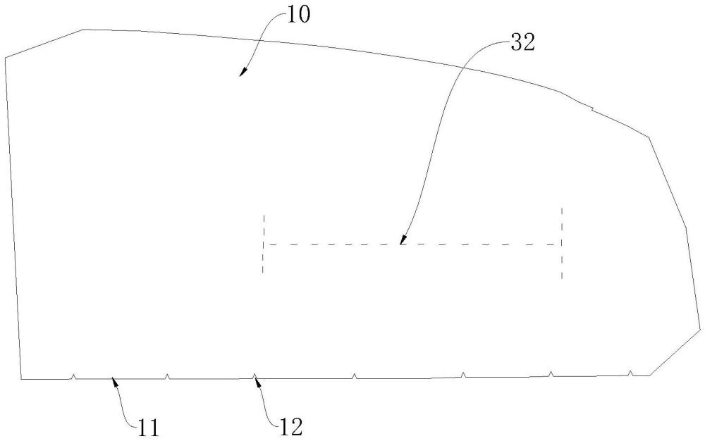
In some embodiments, see Figure 2, the weakening part 32 is located in the middle region of the first epidermis 10 and has an I-shaped structure. Thus, setting the weakening section 32 in an I-shaped structure can achieve uniform stress distribution, improve tensile strength, provide a stable tear path, and adapt to complex stress conditions.
Specifically, refer to Figure 2. The two flanges of the I-shaped can effectively distribute stress, making stress distribution more uniform and reducing local stress concentration. When the airbag deploys, the force acting on the weakened line area is distributed more evenly across all parts of the I-shape, reducing the risk of tearing caused by stress concentration; The I-shaped shape increases the tensile strength of the weakening section 32, making it more stable and reliable under tensile forces. This helps ensure that during the airbag deployment, the weakening wire can tear in the designated area without accidental breakage or damage; The I-shaped shape provides a clear path for the tearing process, allowing it to proceed stably along a predetermined weakening line. This stable tear path helps the airbag deploy smoothly, ensuring optimal protection as designed; The I-shaped shape allows it to adapt to complex stress conditions, maintaining good performance under tensile, compressive, or shear stresses. This multi-directional stress adaptability helps the attenuated line reliably perform under various collision conditions.
In some embodiments, referring to Figure 1, the first mating edge 11 and the second mating edge 21 are linear edges of the same length. This facilitates the efficiency of laminating the first mating edge 11 and the second joint edge 21.
In the embodiment, referring to Figure 1, the connection method of the first joint edge 11 and the second joint edge 21 can be joined together by sewing.
A type of vehicle that includes non-low-tear skin components and interior parts, with the skin components wrapped around the outer periphery of the interior parts.
Furthermore, the terms "first" and "second" are used only for descriptive purposes and should not be understood as indicating or implying relative importance or implying the quantity of technical features indicated. Thus, features with "first" and "second" can explicitly or implicitly include at least one of these features. In the description of this utility model, "multiple" means at least two, such as two, three, etc., unless otherwise explicitly specified.
In the description of this specification, references to terms such as "one embodiment," "some embodiments," "examples," "specific examples," or "some examples" mean that the specific features, structure, materials, or features described in conjunction with the embodiment or example are included in at least one embodiment or example of this utility model. In this specification, the schematic representation of the above terms does not necessarily refer to the same embodiments or examples. Moreover, the specific features, structures, materials, or features described may be appropriately combined in any or more embodiments or examples. Furthermore, without contradiction, those skilled in the art may combine and combine different embodiments or examples described in this specification and the features of different embodiments or examples.
The above embodiments only express several embodiments of this application, which are relatively specific and detailed, but should not be interpreted as limiting the scope of the utility model patent. It should be noted that for those skilled in the art, various modifications and improvements can be made without departing from the concept of this application, all of which fall within the scope of protection of this application. Therefore, the scope of protection for this patent application shall be based on the attached claims.






 400-4929-0909
 contact@catarc.com.cn

