The specific embodiment
The present invention is described in further detail below in conjunction with the accompanying drawings.
The first embodiment:
Referring to FIG. 1, a planetary multi-stage transmission transmission mechanism comprises input shaft IN, output shaft OUT, the first planetary row P1, the second planetary row P2 and the third planetary row P3;
The input shaft IN is connected with the first planetary row P1; The output shaft OUT is connected with the second planetary row P2;
The first planetary row P1 comprises the first sun gear S1, the first planetary carrier PC1, the first planetary wheel CA1 and the first gear ring R1; the first planetary wheel CA1 is movably mounted on the first planetary carrier PC1, the first gear ring R1 is meshed with the first planetary wheel CA1, and the first planetary wheel CA1 is meshed with the first sun wheel S1;
the second planet row P2 comprises a second sun gear S2, a second planet carrier PC2, a second planet wheel CA2 and a second gear ring R2; the second planet wheel CA2 is movably mounted on the second planet carrier PC2, the second gear ring R2 is meshed with the second planet wheel CA2, and the second planet wheel CA2 is meshed with the second sun wheel S2;
the third planet row P3 comprises the third sun gear S3, the third planet carrier PC3, the third planet wheel CA3 and the third gear ring R3; the third planet wheel CA3 is movably installed on the third planet carrier PC3, the third gear ring R3 is meshed with the third planet wheel CA3, and the third planet wheel CA3 is meshed with the third sun wheel S3;
the third sun gear S3 is movably arranged on the planet carrier connecting shaft L3; The first planetary carrier PC1 and the second planetary carrier PC2 are fixedly connected through the planetary carrier connecting shaft L3.
input shaft IN is fixedly connected with the first sun gear S1, the first gear ring R1 is fixedly connected with the third sun gear S3 through the first connecting piece L1, the third gear ring R3 is fixedly connected with the second gear ring R2 through the second connecting piece L2, and the output shaft OUT is fixedly connected with the second sun gear S2;
The first gear ring R1 is connected with the first brake B1, that is, the first brake B1 can brake the first gear ring R1; The second gear ring R2 is connected with the second brake B2, that is, the second brake B2 can brake the second gear ring R2; the second planetary carrier PC2 is connected with the planetary carrier brake BL3, that is, the planetary carrier brake BL3 can brake the second planetary carrier PC2; The third planetary carrier PC3 is connected with the third brake B3, that is, the third brake B3 can brake the third planetary carrier PC3.
Among them, the movable installation can be understood as a rotating connection; A fixed connection can be understood as a linkage connection.
Working principle: ring gear is connected to the sun gear, ring gear is connected to ring gear, RS-RR type.
The first brake B1 is engaged with the second brake B2 at the same time, the first gear ring R1 and the second gear ring R2 are fixed respectively, and the first sun gear S1 is fixedly connected with input shaft N, and rotates in the same direction and speed; In the first planetary row P1, the first sun gear S1 inputs power, the first gear ring R1 is fixed, and the first planetary carrier PC1 rotates in the same direction with the input shaft I N; in the second planetary row P2, the second planetary carrier PC2 is fixedly connected with the first planetary carrier PC1 through the planetary carrier connecting shaft L3, the second planetary carrier PC2 input power, the second gear ring R2 is fixed, the second sun gear S2 is fixedly connected with the output shaft OUT, the second sun gear S2 outputs power to the output shaft OUT, and the output shaft OUT is the same as the input shaft I N rotation direction; The power passes through the first planetary row P1, the planetary carrier connecting shaft L3 and the second planetary row P2 in turn, realizes the two-stage transmission, and the direction of rotation of the output power is the same as that of the input power.
The third brake B3 is engaged with the planetary carrier brake BL3 at the same time, the first planetary carrier PC1, the second planetary carrier PC2 and the third planetary carrier PC3 are fixed respectively, and the first sun gear S1 is fixedly connected with the input shaft IN and rotates in the same direction and speed; In the first planetary row P1, the first sun gear S1 inputs power, the first planetary carrier PC1 is fixed, and the first gear ring R1 rotates in the opposite direction with the input shaft IN; The first gear ring R1 is fixedly connected with the third sun gear S3 through the first connecting piece L1, and in the third planetary row P3, the third sun gear S3 input power, the third planet carrier PC3 is fixed, and the third gear ring R3 rotates in the same direction with the input shaft IN; The third gear ring R3 is fixedly connected with the second gear ring R2 through the second connecting piece L2, in the second planetary row P2, the second gear ring R2 input power, the second planetary carrier PC2 is fixed, the second sun gear S2 and the input shaft I N rotate in the opposite direction, the second sun gear S2 is fixedly connected with the output shaft OUT, the second sun gear S2 outputs power to the output shaft OUT, and the output shaft OUT is opposite to the input shaft IN rotation direction; The power passes through the first planetary row P1, the first connecting piece L1, the third planetary row P3, the second connecting piece L2 and the second planetary row P2 in turn, realizes three-stage transmission, and the direction of rotation of output power is opposite to the direction of rotation of input power.
The third brake B3 is individually engaged, the third planetary carrier PC3 is fixed, the first planetary row P1, the second planetary row P2 and the third planetary row P3 are combined into a planetary row group with two degrees of freedom, and the power is divided into a two-stage transmission and a three-stage transmission, and a mixed transmission is realized; The first sun gear S1 is fixedly connected with the input shaft I N and rotates in the same direction and speed; In the first planetary row P1, the first sun gear S1 inputs power, and the power shunt is a two-way transmission, the first road is transmitted in the mode of two-stage transmission through the first planetary carrier PC1, and the second road is transmitted in the mode of three-stage transmission through the first ring gear R1; In the first planetary row P1, the first sun gear S1 will output power to the first planet carrier PC1, the first planet carrier PC1 will output power to the planet carrier connecting shaft L3, in the second planet row P2, the planet carrier connecting shaft L3 will output power to the second planet carrier PC2, and the second planet carrier PC2 power is respectively output to the second gear ring R2 and the second sun gear S2 after the second planet carrier PC2 power is shunted again; The second way transmission, in the first planetary row P1, the first sun gear S1 outputs power to the first gear ring R1 through the first planet wheel CA1, the first gear ring R1 will output power to the first connecting piece L1, in the third planet row P3, the first connecting piece L1 will output power to the third sun gear S3, the third sun gear S3 will output power to the third gear ring R3 through the third planet wheel CA3, the third gear ring R3 will output power to the second connecting piece L2, in the second planet row P2, the second connecting piece L2 outputs power to the second gear ring R2, and the second gear ring R2 power is output to the second planetary carrier PC2 and the second sun gear S2 respectively after the second gear R2 power is shunted again; The planetary row group with two degrees of freedom realizes the hybrid transmission of two-stage transmission in parallel and three-stage transmission, and activates one control piece to eliminate another degree of freedom, so as to realize fixed input and output.
Second embodiment:
Referring to FIG. 2, a planetary multi-stage transmission transmission mechanism comprises input shaft IN, output shaft OUT, the first planetary row P1, the second planetary row P2 and the third planetary row P3;
The input shaft IN is connected with the first planetary row P1; The output shaft OUT is connected with the second planetary row P2;
The first planetary row P1 comprises the first sun gear S1, the first planetary carrier PC1, the first planetary wheel CA1 and the first gear ring R1; the first planetary wheel CA1 is movably mounted on the first planetary carrier PC1, the first gear ring R1 is meshed with the first planetary wheel CA1, and the first planetary wheel CA1 is meshed with the first sun wheel S1;
the second planet row P2 comprises a second sun gear S2, a second planet carrier PC2, a second planet wheel CA2 and a second gear ring R2; the second planet wheel CA2 is movably mounted on the second planet carrier PC2, the second gear ring R2 is meshed with the second planet wheel CA2, and the second planet wheel CA2 is meshed with the second sun wheel S2;
the third planet row P3 comprises the third sun gear S3, the third planet carrier PC3, the third planet wheel CA3 and the third gear ring R3; the third planet wheel CA3 is movably installed on the third planet carrier PC3, the third gear ring R3 is meshed with the third planet wheel CA3, and the third planet wheel CA3 is meshed with the third sun wheel S3;
the second sun gear S2 and the third sun gear S3 are both movably mounted on the planetary carrier connecting shaft L3; The first planetary carrier PC1 and the second planetary carrier PC2 are fixedly connected through the planetary carrier connecting shaft L3;
input shaft IN is fixedly connected with the first sun gear S1, the first gear ring R1 is fixedly connected with the third gear ring R3 through the first connecting piece L1, the third sun gear S3 is fixedly connected with the second sun gear S2 through the second connecting piece L2, and the output shaft OUT is fixedly connected with the second gear ring R2;
The first gear ring R1 is connected with the first brake B1, that is, the first brake B1 can brake the first gear ring R1; The second sun gear S2 is connected with the second brake B2, that is, the second brake B2 can brake the second sun gear S2; the second planetary carrier PC2 is connected with the planetary carrier brake BL3, that is, the planetary carrier brake BL3 can brake the second planetary carrier PC2; The third planetary carrier PC3 is connected with the third brake B3, that is, the third brake B3 can brake the third planetary carrier PC3.
Working principle: ring gear is connected to ring gear, sun gear is connected to sun gear, RR-SS type.
The first brake B1 is engaged with the second brake B2 simultaneously, the first gear ring R1 and the second sun gear S2 are fixed respectively, and the first sun gear S1 is fixedly connected with input shaft IN and rotates in the same direction and speed; In the first planetary row P1, the first sun gear S1 inputs power, the first gear ring R1 is fixed, and the first planetary carrier PC1 rotates in the same direction with the input shaft IN; in the second planetary row P2, the second planetary carrier PC2 is fixedly connected with the first planetary carrier PC1 through the planetary carrier connecting shaft L3, the second planetary carrier PC2 input power, the second sun gear S2 is fixed, the second gear ring R2 is fixedly connected with the output shaft OUT, the second gear ring R2 outputs power to the output shaft OUT, and the output shaft OUT and the input shaft IN rotate in the same direction; The power passes through the first planetary row P1, the planetary carrier connecting shaft L3 and the second planetary row P2 in turn, realizes the two-stage transmission, and the direction of rotation of the output power is the same as that of the input power.
The third brake B3 is engaged with the planetary carrier brake BL3 at the same time, the first planetary carrier PC1, the second planetary carrier PC2 and the third planetary carrier PC3 are fixed respectively, and the first sun gear S1 is fixedly connected with the input shaft IN and rotates in the same direction and speed; In the first planetary row P1, the first sun gear S1 inputs power, the first planetary carrier PC1 is fixed, and the first gear ring R1 rotates in the opposite direction with the input shaft IN; The first gear ring R1 is fixedly connected with the third gear ring R3 through the first connecting piece L1, and in the third planetary row P3, the third gear ring R3 input power, the third planet carrier PC3 is fixed, and the third sun gear S3 rotates in the same direction with the input shaft IN; the third sun gear S3 and the second sun gear S2 are fixedly connected through the second connecting piece L2, in the second planetary row P2, the second sun gear S2 input power, the second planetary carrier PC2 is fixed, the second gear ring R2 rotates in reverse with the input shaft IN, the second gear ring R2 is fixedly connected with the output shaft OUT, the second gear ring R2 outputs the power to the output shaft OUT, and the output shaft OUT is opposite to the input shaft IN rotation direction; The power passes through the first planetary row P1, the first connecting piece L1, the third planetary row P3, the second connecting piece L2 and the second planetary row P2 in turn, realizes three-stage transmission, and the direction of rotation of output power is opposite to the direction of rotation of input power.
The third brake B3 is individually engaged, the third planetary carrier PC3 is fixed, and the first planetary row P1, the second planetary row P2 and the third planetary row P3 are combined into a planetary row group with two degrees of freedom, and the mixed transmission of two-stage transmission parallel three-stage transmission is realized; The first sun gear S1 is fixedly connected with the input shaft IN and rotates in the same direction and speed; In the first planetary row P1, the first sun gear S1 inputs power, and the power shunt is a two-way transmission, the first road is transmitted in the mode of two-stage transmission through the first planetary carrier PC1, and the second road is transmitted in the mode of three-stage transmission through the first ring gear R1; In the first planetary row P1, the first sun gear S1 will output power to the first planet carrier PC1, the first planet carrier PC1 will output power to the planet carrier connecting shaft L3, in the second planet row P2, the planet carrier connecting shaft L3 will output power to the second planet carrier PC2, and the second planet carrier PC2 power is respectively output to the second gear ring R2 and the second sun gear S2 after the second planet carrier PC2 power is shunted again; The second way transmission, in the first planetary row P1, the first sun gear S1 outputs power to the first gear ring R1 through the first planet wheel CA1, the first gear ring R1 will output power to the first connecting piece L1, in the third planetary row P3, the first connecting piece L1 will output power to the third gear ring R3, the third gear gear R3 will output power to the third sun gear S3 through the third planet wheel CA3, the third sun gear S3 will output power to the second connecting piece L2, in the second planet row P2, the second connecting piece L2 outputs power to the second sun gear S2, and the second sun gear S2 outputs the power to the second planetary carrier PC2 and the second gear ring R2 respectively after the power is shunted again; The planetary row group with two degrees of freedom realizes the hybrid transmission of two-stage transmission in parallel and three-stage transmission, and activates one control piece to eliminate another degree of freedom, so as to realize fixed input and output.
3rd embodiment:
Referring to FIG. 3, a planetary multistage transmission variable speed mechanism comprises input shaft IN, output shaft OUT, the first planetary row P1, the second planetary row P2 and the third planetary row P3;
The input shaft IN is connected with the first planetary row P1; The output shaft OUT is connected with the second planetary row P2;
The first planetary row P1 comprises the first sun gear S1, the first planetary carrier PC1, the first planetary wheel CA1 and the first gear ring R1; the first planetary wheel CA1 is movably mounted on the first planetary carrier PC1, the first gear ring R1 is meshed with the first planetary wheel CA1, and the first planetary wheel CA1 is meshed with the first sun wheel S1;
the second planet row P2 comprises a second sun gear S2, a second planet carrier PC2, a second planet wheel CA2 and a second gear ring R2; the second planet wheel CA2 is movably mounted on the second planet carrier PC2, the second gear ring R2 is meshed with the second planet wheel CA2, and the second planet wheel CA2 is meshed with the second sun wheel S2;
the third planet row P3 comprises the third sun gear S3, the third planet carrier PC3, the third planet wheel CA3 and the third gear ring R3; the third planet wheel CA3 is movably installed on the third planet carrier PC3, the third gear ring R3 is meshed with the third planet wheel CA3, and the third planet wheel CA3 is meshed with the third sun wheel S3;
the second sun gear S2 and the third sun gear S3 are both movably mounted on the planetary carrier connecting shaft L3; The first planetary carrier PC1 and the second planetary carrier PC2 are fixedly connected through the planetary carrier connecting shaft L3;
input shaft IN is fixedly connected with the first sun gear S1, the first gear ring R1 is fixedly connected with the third sun gear S3 through the first connecting piece L1, the third gear ring R3 is fixedly connected with the second sun gear S2 through the second connecting piece L2, and the output shaft OUT is fixedly connected with the second gear ring R2;
The first gear ring R1 is connected with the first brake B1, that is, the first brake B1 can brake the first gear ring R1; The second sun gear S2 is connected with the second brake B2, that is, the second brake B2 can brake the second sun gear S2; the second planetary carrier PC2 is connected with the planetary carrier brake BL3, that is, the planetary carrier brake BL3 can brake the second planetary carrier PC2; The third planetary carrier PC3 is connected with the third brake B3, that is, the third brake B3 can brake the third planetary carrier PC3.
Working principle: ring gear is connected to the sun gear, ring gear is connected to the sun gear, RS-RS type.
The first brake B1 is engaged with the second brake B2 simultaneously, the first gear ring R1 and the second sun gear S2 are fixed respectively, and the first sun gear S1 is fixedly connected with input shaft IN and rotates in the same direction and speed; In the first planetary row P1, the first sun gear S1 inputs power, the first gear ring R1 is fixed, and the first planetary carrier PC1 rotates in the same direction with the input shaft IN; in the second planetary row P2, the second planetary carrier PC2 is fixedly connected with the first planetary carrier PC1 through the planetary carrier connecting shaft L3, the second planetary carrier PC2 input power, the second sun gear S2 is fixed, the second gear ring R2 is fixedly connected with the output shaft OUT, the second gear ring R2 outputs power to the output shaft OUT, and the output shaft OUT and the input shaft IN rotate in the same direction; The power passes through the first planetary row P1, the planetary carrier connecting shaft L3 and the second planetary row P2 in turn, realizes the two-stage transmission, and the direction of rotation of the output power is the same as that of the input power.
The third brake B3 is engaged with the planetary carrier brake BL3 at the same time, the first planetary carrier PC1, the second planetary carrier PC2 and the third planetary carrier PC3 are fixed respectively, and the first sun gear S1 is fixedly connected with the input shaft IN and rotates in the same direction and speed; In the first planetary row P1, the first sun gear S1 inputs power, the first planetary carrier PC1 is fixed, and the first gear ring R1 rotates in the opposite direction with the input shaft IN; The first gear ring R1 is fixedly connected with the third sun gear S3 through the first connecting piece L1, and in the third planetary row P3, the third sun gear S3 input power, the third planet carrier PC3 is fixed, and the third gear ring R3 rotates in the same direction with the input shaft IN; The third gear ring R3 is fixedly connected with the second sun gear S2 through the second connecting piece L2, in the second planetary row P2, the second sun gear S2 input power, the second planet carrier PC2 is fixed, the second gear ring R2 rotates in reverse with the input shaft IN, the second gear ring R2 is fixedly connected with the output shaft OUT, the second gear ring R2 outputs the power to the output shaft OUT, and the output shaft OUT is opposite to the direction of rotation of the input shaft IN; The power passes through the first planetary row P1, the first connecting piece L1, the third planetary row P3, the second connecting piece L2 and the second planetary row P2 in turn, realizes three-stage transmission, and the direction of rotation of output power is opposite to the direction of rotation of input power.
The third brake B3 is individually engaged, the third planetary carrier PC3 is fixed, and the first planetary row P1, the second planetary row P2 and the third planetary row P3 are combined into a planetary row group with two degrees of freedom, and the mixed transmission of two-stage transmission parallel three-stage transmission is realized; The first sun gear S1 is fixedly connected with the input shaft IN and rotates in the same direction and speed; In the first planetary row P1, the first sun gear S1 inputs power, and the power shunt is a two-way transmission, the first road is transmitted in the mode of two-stage transmission through the first planetary carrier PC1, and the second road is transmitted in the mode of three-stage transmission through the first ring gear R1; In the first planetary row P1, the first sun gear S1 will output power to the first planet carrier PC1, the first planet carrier PC1 will output power to the planet carrier connecting shaft L3, in the second planet row P2, the planet carrier connecting shaft L3 will output power to the second planet carrier PC2, and the second planet carrier PC2 power is respectively output to the second gear ring R2 and the second sun gear S2 after the second planet carrier PC2 power is shunted again; The second way transmission, in the first planetary row P1, the first sun gear S1 outputs power to the first gear ring R1 through the first planet wheel CA1, the first gear ring R1 will output power to the first connecting piece L1, in the third planet row P3, the first connecting piece L1 will output power to the third sun gear S3, the third sun gear S3 will output power to the third gear ring R3 through the third planet wheel CA3, the third gear ring R3 will output power to the second connecting piece L2, in the second planet row P2, the second connecting piece L2 outputs power to the second sun gear S2, and the second sun gear S2 outputs the power to the second planetary carrier PC2 and the second gear ring R2 respectively after the power is shunted again; The planetary row group with two degrees of freedom realizes the hybrid transmission of two-stage transmission in parallel and three-stage transmission, and activates one control piece to eliminate another degree of freedom, so as to realize fixed input and output.
Fourth embodiment:
Referring to FIG. 4, a planetary multistage transmission variable speed mechanism comprises input shaft IN, output shaft OUT, the first planetary row P1, the second planetary row P2 and the third planetary row P3;
The input shaft IN is connected with the first planetary row P1; The output shaft OUT is connected with the second planetary row P2;
The first planetary row P1 comprises the first sun gear S1, the first planetary carrier PC1, the first planetary wheel CA1 and the first gear ring R1; the first planetary wheel CA1 is movably mounted on the first planetary carrier PC1, the first gear ring R1 is meshed with the first planetary wheel CA1, and the first planetary wheel CA1 is meshed with the first sun wheel S1;
the second planet row P2 comprises a second sun gear S2, a second planet carrier PC2, a second planet wheel CA2 and a second gear ring R2; the second planet wheel CA2 is movably mounted on the second planet carrier PC2, the second gear ring R2 is meshed with the second planet wheel CA2, and the second planet wheel CA2 is meshed with the second sun wheel S2;
the third planet row P3 comprises the third sun gear S3, the third planet carrier PC3, the third planet wheel CA3 and the third gear ring R3; the third planet wheel CA3 is movably installed on the third planet carrier PC3, the third gear ring R3 is meshed with the third planet wheel CA3, and the third planet wheel CA3 is meshed with the third sun wheel S3;
the first sun gear S1, the second sun gear S2 and the third sun gear S3 are all movably mounted on the planet carrier connecting shaft L3; The first planetary carrier PC1 and the second planetary carrier PC2 are fixedly connected through the planetary carrier connecting shaft L3;
input shaft IN is fixedly connected with first gear ring R1, first sun gear S1 is fixedly connected with third sun gear S3 by first connecting piece L1, third gear ring R3 is fixedly connected with second sun gear S2 by second connecting piece L2, and output shaft OUT is fixedly connected with second gear ring R2;
The first sun gear S1 is connected with the first brake B1, that is, the first brake B1 can brake the first sun wheel S1; The second sun gear S2 is connected with the second brake B2, that is, the second brake B2 can brake the second sun gear S2; the second planetary carrier PC2 is connected with the planetary carrier brake BL3, that is, the planetary carrier brake BL3 can brake the second planetary carrier PC2; The third planetary carrier PC3 is connected with the third brake B3, that is, the third brake B3 can brake the third planetary carrier PC3.
Working principle: the sun gear is connected to the sun gear, and the ring gear is connected to the sun gear, SS-RS type.
The first brake B1 is engaged with the second brake B2 at the same time, the first sun gear S1 and the second sun gear S2 are fixed respectively, and the first gear ring R1 is fixedly connected with input shaft IN and rotates in the same direction and speed; In the first planetary row P1, the first gear ring R1 inputs power, the first sun gear S1 is fixed, and the first planetary carrier PC1 rotates in the same direction with the input shaft IN; in the second planetary row P2, the second planetary carrier PC2 is fixedly connected with the first planetary carrier PC1 through the planetary carrier connecting shaft L3, the second planetary carrier PC2 input power, the second sun gear S2 is fixed, the second gear ring R2 is fixedly connected with the output shaft OUT, the second gear ring R2 outputs power to the output shaft OUT, and the output shaft OUT and the input shaft IN rotate in the same direction; The power passes through the first planetary row P1, the planetary carrier connecting shaft L3 and the second planetary row P2 in turn, realizes the two-stage transmission, and the direction of rotation of the output power is the same as that of the input power.
The third brake B3 is engaged with the planetary carrier brake BL3 simultaneously, the first planetary carrier PC1, the second planetary carrier PC2 and the third planetary carrier PC3 are fixed respectively, and the first gear ring R1 is fixedly connected with the input shaft IN and rotates in the same direction and speed; In the first planetary row P1, the first gear ring R1 inputs power, the first planet carrier PC1 is fixed, and the first sun gear S1 rotates in reverse with input shaft I N; The first sun gear S1 and the third sun gear S3 are fixedly connected through the first connecting piece L1, and in the third planetary row P3, the third sun gear S3 input power, the third planet carrier PC3 is fixed, and the third gear ring R3 rotates in the same direction with input shaft IN; The third gear ring R3 is fixedly connected with the second sun gear S2 through the second connecting piece L2, in the second planetary row P2, the second sun gear S2 input power, the second planet carrier PC2 is fixed, the second gear ring R2 rotates in reverse with the input shaft IN, the second gear ring R2 is fixedly connected with the output shaft OUT, the second gear ring R2 outputs the power to the output shaft OUT, and the output shaft OUT is opposite to the direction of rotation of the input shaft IN; The power passes through the first planetary row P1, the first connecting piece L1, the third planetary row P3, the second connecting piece L2 and the second planetary row P2 in turn, realizes three-stage transmission, and the direction of rotation of output power is opposite to the direction of rotation of input power.
The third brake B3 is individually engaged, the third planetary carrier PC3 is fixed, and the first planetary row P1, the second planetary row P2 and the third planetary row P3 are combined into a planetary row group with two degrees of freedom, and the mixed transmission of two-stage transmission parallel three-stage transmission is realized; The first gear ring R1 is fixedly connected with the input shaft IN and rotates in the same direction and speed; In the first planetary row P1, the first gear ring R1 inputs power, and the power shunt is a two-way transmission, the first is transmitted in the mode of two-stage transmission through the first planetary carrier PC1, and the second is transmitted in the mode of three-stage transmission through the first sun gear S1; In the first planetary row P1, the first gear ring R1 will output power to the first planet carrier PC1, the first planet carrier PC1 will power output to the planet carrier connecting shaft L3, in the second planet row P2, the planet carrier connecting shaft L3 will output power to the second planet carrier PC2, and the second planet carrier PC2 power is respectively output to the second gear ring R2 and the second sun gear S2 after the second planet carrier PC2 power is shunted again; The second way transmission, in the first planetary row P1, the first gear ring R1 outputs power to the first sun gear S1 through the first planet gear CA1, the first sun gear S1 outputs power to the first connecting piece L1, in the third planet row P3, the first connecting piece L1 outputs power to the third sun gear S3, the third sun gear S3 outputs power to the third gear ring R3 through the third planet gear CA3, the third gear ring R3 outputs power to the second connecting piece L2, in the second planet row P2, the second connecting piece L2 outputs power to the second sun gear S2, and the second sun gear S2 outputs the power to the second planetary carrier PC2 and the second gear ring R2 respectively after the power is shunted again; The planetary row group with two degrees of freedom realizes the hybrid transmission of two-stage transmission in parallel and three-stage transmission, and activates one control piece to eliminate another degree of freedom, so as to realize fixed input and output.
In the above four embodiments, n1 planetary rows are arranged in parallel on the input shaft IN to form the first planetary row group PZ1; n2 planetary rows are arranged in parallel on the output shaft OUT to form a second planetary row group PZ2; Each of the two planetary rows is equipped with a corresponding brake.
The n1 planetary rows in the first planetary row group PZ1 and the n2 planetary rows in the second planetary row group PZ2 are combined in pairs, and there are n1×n2 combinations, and a pair of brakes on the planetary rows on each combination of n1×n2 combinations brake at the same time, can realize a two-stage transmission, and the rotation direction of power output is the same as the rotation direction of power input, and n1×n2 two-stage transmissions can be realized.
After braking the third brake B3 that is arranged on the third planetary row P3, realize a planetary row group with two degrees of freedom that is made up of the first planetary row P1, the second planetary row P2 and the third planetary row P3, the n1 planetary row on the first planetary row group PZ1, after braking sequentially with the brake that is arranged on the n2 planetary rows on the second planetary row group PZ2, another degree of freedom can be eliminated, the fixed input and output are realized, and the rotation direction of power output is the same as the rotation direction of power input, and n1+ can be realizedn2 two-stage transmissions, parallel three-stage transmissions, mixed transmissions; The third planet row P3 and the first planet row P1, the second planet row P2 with the connection relationship are combined separately, and there are two combinations in total, and the brakes that are arranged on a pair of planetary rows on each combination brake at the same time, only realize the first gear ring R1 (or the first sun gear S1) and the second gear ring R2 (or the second sun gear S2) brake a kind of two-stage transmission result simultaneously, and finally realize (n1-1) + (n2-1) mixed transmission gears with actual transmission efficiency, The direction of rotation of the power take-off is the same as that of the power input.
The third brake B3 is connected with the planetary carrier brake BL3 at the same time, and the power passes through the first planetary row P1, the first connecting piece L1, the third planetary row P3, the second connecting piece L2 and the second planetary row P2 in turn, realizes a three-stage transmission, and the output power rotation direction is opposite to the input power rotation direction, and realizes 1 gear.
The planetary multi-stage transmission transmission mechanism is applied to two planetary rows, and the forward gears in the same direction as the power input steering can be n1×n2+(n1-1)+(n2-1), and the number of backward gears in the opposite direction of the power input steering is 1.
The above-mentioned planetary multi-stage transmission transmission mechanism is an application demonstration of the number of planetary rows n1=1 of the first planetary row group PZ1 and the planetary row number n2=1 of the second planetary row group PZ2.
In addition, in the above embodiment, two power flow directions are allowed: first, power flows in from the input shaft N and flows out from the output shaft OUT; In the second case, it flows in from the output shaft OUT and out from the input shaft N .
Brakes such as the first brake B1, the second brake B2, the third brake B3 and the planetary carrier brake BL3 are all friction type control structures.
Fifth embodiment:
Referring to Fig. 5, a planetary type multi-stage transmission transmission mechanism, applying the first embodiment, on the basis of the first embodiment, the fifth planetary row P5, the fourth planetary row P4 and the sixth planetary row P6 are added; Arrangement: the fifth planet row P5, the first planet row P1, the third planet row P3, the second planet row P2, the fourth planet row P4 and the sixth planet row P6 are distributed in sequence;
The fifth planetary row P5 comprises the fifth sun gear S5, the fifth planetary carrier PC5, the fifth planetary wheel CA5 and the fifth ring gear R5, the fifth planet wheel CA5 is movably installed on the fifth planet carrier PC5, the fifth ring gear R5 is meshed with the fifth planet wheel CA5, the fifth planetary wheel CA5 is meshed with the fifth sun gear S5, and the fifth ring gear R5 realizes braking through the fifth brake B5.
The first planetary row P1 comprises the first sun gear S1, the first planetary carrier PC1, the first planetary wheel CA1 and the first ring gear R1, the first planet wheel CA1 is movably mounted on the first planet carrier PC1, the first ring gear R1 is meshed with the first planet wheel CA1, the first planetary wheel CA1 is meshed with the first sun wheel S1, and the first ring gear R1 realizes braking through the first brake B1.
The third planet row P3 comprises the third sun gear S3, the third planet carrier PC3, the third planet wheel CA3 and the third gear ring R3, the third planet wheel CA3 is movably installed on the third planet carrier PC3, the third gear ring R3 is meshed with the third planet wheel CA3, the third planet gear CA3 is meshed with the third sun gear S3, the third sun gear S3 is movably installed on the planet carrier connecting shaft L3, and the third planet carrier PC3 realizes braking through the third brake B3.
The second planet row P2 comprises the second sun gear S2, the second planet carrier PC2, the second planet wheel CA2 and the second ring gear R2, the second planet wheel CA2 is movably installed on the second planet carrier PC2, the second ring gear R2 is meshed with the second planet wheel CA2, the second planet wheel CA2 is meshed with the second sun gear S2, and the second ring gear R2 realizes braking through the second brake B2.
The fourth planet row P4 comprises the fourth sun gear S4, the fourth planet carrier PC4, the fourth planet wheel CA4 and the fourth gear ring R4, the fourth planet wheel CA4 is movably installed on the fourth planet carrier PC4, the fourth gear ring R4 is meshed with the fourth planet wheel CA4, the fourth planet wheel CA4 is meshed with the fourth sun wheel S4, and the fourth gear ring R4 realizes braking through the fourth brake B4.
The sixth planet row P6 comprises the sixth sun gear S6, the sixth planet carrier PC6, the sixth planet wheel CA6 and the sixth gear ring R6, the sixth planet wheel CA6 is movably installed on the sixth planet carrier PC6, the sixth gear ring R6 is meshed with the sixth planet wheel CA6, the sixth planetary wheel CA6 is meshed with the sixth sun wheel S6, and the sixth gear ring R6 realizes braking through the sixth brake B6.
The fifth sun gear S5, the first sun gear S1 are fixedly connected with input shaft N N, and the fifth planetary carrier PC5 is fixedly connected with the first planetary carrier PC1; The fifth planet carrier PC5 is provided with planet carrier brake BL3; The planetary carrier brake BL3 can brake the fifth planetary carrier PC5.
The second sun gear S2, the fourth sun gear S4, the sixth sun gear S6 are fixedly connected with the output shaft OUT; The second gear ring R2 is fixedly connected with the fourth planetary carrier PC4 through the fourth connecting piece L4, and the fourth planetary carrier PC4 is fixedly connected with the sixth planetary carrier PC6.
optional, input shaft N, the fifth sun gear S5, the first sun gear S1, the third sun gear S3, the second sun gear S2, the fourth sun gear S4, the sixth sun gear S6 and the output shaft OUT coaxial arrangement; Power flow direction: Power flows in from the input shaft N and out from the output shaft OUT.
The fifth planetary row P5 and the first planetary row P1 constitute the first planetary array PZ1, the number of planetary rows n1=2, the second planetary row P2, the fourth planetary row P4 and the sixth planetary row P6 constitute the second planetary row group PZ2, and the number of planetary rows n2=3; The number of forward gears is n1×n2 + (n1-1) + (n2-1) = 2×3 + (2-1) + (3-1) = 9, and the number of backward gears is 1;
The 3rd brake B3 and the 4th brake B4 are engaged at the same time, and the forward one gear is realized;
The third brake B3 and the sixth brake B6 are engaged at the same time to realize the forward second gear;
The first brake B1 and the fourth brake B4 are engaged at the same time to realize three forward gears;
The first brake B1 and the sixth brake B6 are engaged at the same time, and realize four forward gears;
The fifth brake B5 and the fourth brake B4 are engaged at the same time to realize five forward gears;
The fifth brake B5 and the sixth brake B6 are engaged at the same time to realize the forward six gears;
The first brake B1 and the second brake B2 are engaged at the same time, and realize the forward seven gears;
The fifth brake B5 is engaged with the second brake B2 at the same time, and realizes eight forward gears;
The fifth brake B5 and the third brake B3 are engaged at the same time to realize the forward nine gears;
The planetary carrier brake BL3 and the third brake B3 are engaged at the same time to achieve a backward gear.
The relevant calculation formula is shown in Table 1.1, and the control logic and transmission of each gear are shown in Table 1.2.
Table 1.1 Calculation formula for each gear:
![]()
The ratio of the number of teeth of the first ring gear R1 of the first planetary row P1 to the number of teeth of the first sun gear S1 is K1, and the ratio of the number of teeth of the first planetary row P1 to the sixth planetary row P6 is K1 to K6; When K1=5, K2=6, K3=K4=K5=3, K6=6 in Table 1.1, the input speed is 1, and the transmission ratio of each gear shown in Table 1.1 can be obtained, and the transmission mechanism of nine gears forward and one gear backward is realized.
As shown in Table 1.1, the calculation formula also reveals how the planetary row with two degrees of freedom composed of the first planetary row P1, the second planetary row P2 and the third planetary row P3 when the third brake B3 brakes brakes and expands the transmission ratio range. F1 gear control part B3-B4 combination, compared with the F3 gear control part B1-B4 combination speed formula, the denominator has an additional coefficient (K2+1) composed of K1, K2, K3 ×K1×K3, thereby reducing the speed and increasing the transmission ratio; Compared with the B1-B6 combination speed formula of F4 gear control parts, the same denominator has an additional coefficient (K2+1) composed of K1, K2 and K3 ×K1×K3, thereby reducing the speed and increasing the transmission ratio; F9 gear control part B5-B3 combination, compared with the F8 gear control part B5-B2 combination speed formula, has an additional coefficient [(K1+1)/(K5+1)-1]×K2/K1/K3 composed of K1, K2, K3 and K5, when K1>K5, the coefficient is positive, thereby increasing the speed and reducing the transmission ratio; On the other hand, in order to avoid circulating power, the value of K1 needs to be set to be greater than K5, when the fifth brake B5 brakes, the steering of the first gear ring R1 is the same as the first planetary carrier PC1 steering, and when the third brake B3 is braking, the steering when the power is output to the second gear ring R2 through the first gear ring R1, the first connecting piece L1, the third sun gear S3, the third ring gear R3, the second connecting piece L2 is different from the rotation direction of the second planetary carrier PC2, In addition, the cyclic power occurs when the second gear ring R2 and the second planetary carrier PC2 jointly output power.
Table 1.2 Control logic and transmission ratio of each gear (O indicates the engagement of the control part)
![]()
The examples of the present invention are described in detail below in conjunction with Figure 5 and Table 1.2, and the transmission ratio refers to the ratio of the speed of the input shaft to the speed of the output shaft.
The 3rd brake B3 is engaged with the 4th brake B4 simultaneously, the 3rd planet carrier PC3 and the 4th gear ring R4 are fixed respectively, and the first sun gear S1 is fixedly connected with input shaft I N, and rotates in the same direction and speed; In the first planetary row P1, the first sun gear S1 inputs power, and the power shunt is a two-way transmission, the first road is transmitted in the mode of two-stage transmission through the first planetary carrier PC1, and the second road is transmitted in the mode of three-stage transmission through the first ring gear R1; In the first planetary row P1, the first sun gear S1 will output power to the first planet carrier PC1, the first planet carrier PC1 will output power to the planet carrier connecting shaft L3, in the second planet row P2, the planet carrier connecting shaft L3 will output power to the second planet carrier PC2, and the second planet carrier PC2 power is respectively output to the second gear ring R2 and the second sun gear S2 after the second planet carrier PC2 power is shunted again; The second way transmission, in the first planetary row P1, the first sun gear S1 outputs power to the first gear ring R1 through the first planet wheel CA1, the first gear ring R1 will output power to the first connecting piece L1, in the third planet row P3, the first connecting piece L1 will output power to the third sun gear S3, the third sun gear S3 will output power to the third gear ring R3 through the third planet wheel CA3, the third gear ring R3 will output power to the second connecting piece L2, in the second planet row P2, the second connecting piece L2 outputs power to the second ring gear R2, the second ring gear R2 is fixedly connected with the fourth planetary carrier PC4 through the fourth connecting piece L4, and the second ring gear R2 power is respectively output to the second planetary carrier PC2, the second sun gear S2 and the fourth planetary carrier PC4 after the power is shunted again; The output shaft OUT is a rigid structure, because the fourth gear ring R4 is fixed, the speed ratio of the fourth planetary carrier PC4 and the fourth sun gear S4 is determined, another degree of freedom of the planetary row group has been limited, and finally the second planetary carrier PC2, the second ring gear R2, the fourth planetary carrier PC4 jointly output power to the output shaft OUT through the second sun gear S2 and the fourth sun gear S4, and realize the forward first gear.
The 3rd brake B3 is engaged with the 6th brake B6 at the same time, the 3rd planetary carrier PC3 and the 6th gear ring R6 are fixed respectively, and the first sun gear S1 is fixedly connected with the input shaft I N, and rotates in the same direction and speed; In the first planetary row P1, the first sun gear S1 inputs power, and the power shunt is a two-way transmission, the first road is transmitted in the mode of two-stage transmission through the first planetary carrier PC1, and the second road is transmitted in the mode of three-stage transmission through the first ring gear R1; In the first planetary row P1, the first sun gear S1 will output power to the first planet carrier PC1, the first planet carrier PC1 will output power to the planet carrier connecting shaft L3, in the second planet row P2, the planet carrier connecting shaft L3 will output power to the second planet carrier PC2, and the second planet carrier PC2 power is respectively output to the second gear ring R2 and the second sun gear S2 after the second planet carrier PC2 power is shunted again; The second way transmission, in the first planetary row P1, the first sun gear S1 outputs power to the first gear ring R1 through the first planet wheel CA1, the first gear ring R1 will output power to the first connecting piece L1, in the third planet row P3, the first connecting piece L1 will output power to the third sun gear S3, the third sun gear S3 will output power to the third gear ring R3 through the third planet wheel CA3, the third gear ring R3 will output power to the second connecting piece L2, in the second planet row P2, the second connecting piece L2 outputs power to the second gear ring R2, the second gear ring R2 is fixedly connected with the fourth planetary carrier PC4 and the sixth planetary carrier PC6 through the fourth connecting piece L4, and the second gear ring R2 power is output to the second planetary carrier PC2, the second sun gear S2 and the sixth planetary carrier PC6 respectively after the second gear ring R2 power is shunted again; The output shaft OUT is a rigid structure, because the sixth gear ring R6 is fixed, the speed ratio of the sixth planetary carrier PC6 and the sixth sun gear S6 is determined, another degree of freedom of the planetary row group has been limited, and finally the second planetary carrier PC2, the second ring gear R2, the sixth planetary carrier PC6 jointly output power to the output shaft OUT through the second sun gear S2 and the sixth sun gear S6, and realize the forward second gear.
The first brake B1 is engaged with the 4th brake B4 simultaneously, the first gear ring R1 and the 4th gear ring R4 are fixed respectively, and the first sun gear S1 is fixedly connected with input shaft I N, and rotates in the same direction and speed; In the first planetary row P1, the first sun gear S1 inputs power, and because the first gear ring R1 is fixed, the first planetary carrier PC1 rotates in the same direction with the input shaft I N; The first planetary carrier PC1 is fixedly connected by the planetary carrier connecting shaft L3 and the second planetary carrier PC2, in the second planetary row P2, the second planetary carrier PC2 input power, the second sun gear S2 and the second gear ring R2 output power, and the second sun gear S2 is fixedly connected with the output shaft OUT, and the output shaft is driven to rotate; the second gear ring R2 is fixedly connected with the fourth planetary carrier PC4 through the fourth connecting piece L4, and the second gear ring R2 drives the fourth planetary carrier PC4 to rotate; In the fourth planetary row P4, the fourth gear ring R4 is fixed, and the fourth sun gear S4 outputs power; The output shaft OUT is a rigid structure, and finally the second sun gear S2 and the fourth sun gear S4 jointly output power to the output shaft OUT to achieve three forward gears.
The first brake B1 is engaged with the sixth brake B6 at the same time, the first gear ring R1 and the sixth gear ring R6 are fixed respectively, and the first sun gear S1 is fixedly connected with input shaft I N, and rotates in the same direction and speed; In the first planetary row P1, the first sun gear S1 inputs power, and because the first gear ring R1 is fixed, the first planetary carrier PC1 rotates in the same direction with the input shaft I N; The first planetary carrier PC1 is fixedly connected by the planetary carrier connecting shaft L3 and the second planetary carrier PC2, in the second planetary row P2, the second planetary carrier PC2 input power, the second sun gear S2 and the second gear ring R2 output power, and the second sun gear S2 is fixedly connected with the output shaft OUT, and the output shaft is driven to rotate; the second gear ring R2 is fixedly connected with the fourth planetary carrier PC4 and the sixth planetary carrier PC6 through the fourth connecting piece L4, and the second gear ring R2 drives the sixth planetary carrier PC6 to rotate; In the sixth planetary row P6, the sixth gear ring R6 is fixed, and the sixth sun gear S6 outputs power; The output shaft OUT is a rigid structure, and finally the second sun gear S2 and the sixth sun gear S6 jointly output power to the output shaft OUT to achieve four forward gears.
The fifth brake B5 is engaged with the fourth brake B4 simultaneously, the fifth gear ring R5 and the fourth gear ring R4 are fixed respectively, and the fifth sun gear S5 is fixedly connected with input shaft I N, and rotates in the same direction and speed; In the fifth planetary row P5, the fifth sun gear S5 input power, because the fifth gear ring R5 is fixed, the fifth planetary carrier PC5 is fixedly connected with the first planetary carrier PC1, and the first planetary carrier PC1 rotates in the same direction with the input shaft IN; The first planetary carrier PC1 is fixedly connected by the planetary carrier connecting shaft L3 and the second planetary carrier PC2, in the second planetary row P2, the second planetary carrier PC2 input power, the second sun gear S2 and the second gear ring R2 output power, and the second sun gear S2 is fixedly connected with the output shaft OUT, and the output shaft is driven to rotate; the second gear ring R2 is fixedly connected with the fourth planetary carrier PC4 through the fourth connecting piece L4, and the second gear ring R2 drives the fourth planetary carrier PC4 to rotate; In the fourth planetary row P4, the fourth gear ring R4 is fixed, and the fourth sun gear S4 outputs power; The output shaft OUT is a rigid structure, and finally the second sun gear S2 and the fourth sun gear S4 jointly output power to the output shaft OUT to achieve five forward gears.
The 5th brake B5 and the 6th brake B6 are engaged simultaneously, the 5th gear ring R5 and the 6th gear ring R6 are fixed respectively, and the 5th sun gear S5 is fixedly connected with input shaft I N, and rotates in the same direction and speed; In the fifth planetary row P5, the fifth sun gear S5 input power, because the fifth gear ring R5 is fixed, the fifth planetary carrier PC5 is fixedly connected with the first planetary carrier PC1, and the first planetary carrier PC1 rotates in the same direction with the input shaft IN; The first planetary carrier PC1 is fixedly connected by the planetary carrier connecting shaft L3 and the second planetary carrier PC2, in the second planetary row P2, the second planetary carrier PC2 input power, the second sun gear S2 and the second gear ring R2 output power, and the second sun gear S2 is fixedly connected with the output shaft OUT, and the output shaft is driven to rotate; the second gear ring R2 is fixedly connected with the fourth planetary carrier PC4 and the sixth planetary carrier PC6 through the fourth connecting piece L4, and the second gear ring R2 drives the sixth planetary carrier PC6 to rotate; In the sixth planetary row P6, the sixth gear ring R6 is fixed, and the sixth sun gear S6 outputs power; The output shaft OUT is a rigid structure, and finally the second sun gear S2 and the sixth sun gear S6 jointly output power to the output shaft OUT to achieve six forward gears.
The first brake B1 is engaged with the second brake B2 at the same time, the first gear ring R1 and the second gear ring R2 are fixed respectively, and the first sun gear S1 is fixedly connected with input shaft N, and rotates in the same direction and speed; In the first planetary row P1, the first sun gear S1 inputs power, and because the first gear ring R1 is fixed, the first planetary carrier PC1 rotates in the same direction with the input shaft I N; The first planetary carrier PC1 is fixedly connected by the planetary carrier connecting shaft L3 and the second planetary carrier PC2, in the second planetary row P2, the second planetary carrier PC2 inputs power, the second gear ring R2 is fixed, and the second sun gear S2 outputs power to the output shaft OUT, realizes forward seven gears.
The fifth brake B5 is engaged with the second brake B2 simultaneously, the fifth gear ring R5 and the second gear ring R2 are fixed respectively, and the fifth sun gear S5 is fixedly connected with input shaft I N, and rotates in the same direction and speed; In the fifth planetary row P5, the fifth sun gear S5 input power, because the fifth gear ring R5 is fixed, the fifth planetary carrier PC5 is fixedly connected with the first planetary carrier PC1, and the first planetary carrier PC1 rotates in the same direction with the input shaft IN; The first planetary carrier PC1 is fixedly connected by the planetary carrier connecting shaft L3 and the second planetary carrier PC2, in the second planetary row P2, the second planetary carrier PC2 inputs power, the second gear ring R2 is fixed, and the second sun gear S2 outputs power to the output shaft OUT, and realizes eight forward gears.
The 5th brake B5 is engaged with the 3rd brake B3 simultaneously, the 5th gear ring R5 and the 3rd planet carrier PC3 are fixed respectively, and the 5th sun gear S5 is fixedly connected with input shaft I N, and rotates in the same direction and speed; In the fifth planetary row P5, the fifth sun gear S5 input power, because the fifth gear ring R5 is fixed, the fifth planetary carrier PC5 speed is determined, and rotates in the same direction with the input shaft IN; In the first planetary row P1, the first sun gear S1 inputs power, and the power shunt is a two-way transmission, the first road is transmitted in the mode of two-stage transmission through the first planetary carrier PC1, and the second road is transmitted in the mode of three-stage transmission through the first ring gear R1; In the first planetary row P1, the first sun gear S1 will output power to the first planet carrier PC1, the first planet carrier PC1 will output power to the planet carrier connecting shaft L3, in the second planet row P2, the planet carrier connecting shaft L3 will output power to the second planet carrier PC2, and the second planet carrier PC2 power is respectively output to the second gear ring R2 and the second sun gear S2 after the second planet carrier PC2 power is shunted again; The second way transmission, in the first planetary row P1, the first sun gear S1 outputs power to the first gear ring R1 through the first planet wheel CA1, the first gear ring R1 will output power to the first connecting piece L1, in the third planet row P3, the first connecting piece L1 will output power to the third sun gear S3, the third sun gear S3 will output power to the third gear ring R3 through the third planet wheel CA3, the third gear ring R3 will output power to the second connecting piece L2, in the second planet row P2, the second connecting piece L2 outputs power to the second gear ring R2, and the second gear ring R2 power is output to the second planetary carrier PC2 and the second sun gear S2 respectively after the second gear R2 power is shunted again; Because the fifth gear ring R5 is fixed, the speed of the fifth planetary carrier PC5 is determined, another degree of freedom of the planetary row group has been limited, and finally the second planetary carrier PC2 and the second gear ring R2 jointly output power to the output shaft OUT through the second sun gear S2, and realize the forward nine gears.
Planetary carrier brake BL3 is engaged with the third brake B3 simultaneously, the fifth planetary carrier PC5, the first planetary carrier PC1, the second planetary carrier PC2 and the third planetary carrier PC3 are fixed respectively, and the first sun gear S1 is fixedly connected with input shaft I N, and rotates in the same direction and speed; In the first planetary row P1, the first sun gear S1 inputs power, the first planetary carrier PC1 is fixed, and the first gear ring R1 rotates in the opposite direction with the input shaft IN; The first gear ring R1 is fixedly connected with the third sun gear S3 through the first connecting piece L1, and in the third planetary row P3, the third sun gear S3 input power, the third planet carrier PC3 is fixed, and the third gear ring R3 rotates in the same direction with the input shaft IN; The third gear ring R3 is fixedly connected with the second gear ring R2 through the second connecting piece L2, in the second planetary row P2, the second gear ring R2 input power, the second planet carrier PC2 is fixed, the second sun gear S2 and the input shaft IN rotate in the opposite direction, the second sun gear S2 is fixedly connected with the output shaft OUT, and the second sun gear S2 outputs power to the output shaft OUT, and realizes a backward gear.
The transmission ratio of each gear is determined by the K value of the six planetary rows, and the K value of the planetary row refers to the ratio of the number of ring gear teeth of the planetary row to the number of sun gear teeth, for example, when K1=5, K2=6, K3=K4=K5=3, K6=6, The transmission ratio of each gear shown in Table 1.1 can be obtained, and the transmission mechanism of nine gears forward and one gear backward is realized, and the speed ratio of one gear is greater than 5, which can reduce the load of the torque converter when the vehicle is at low speed, improve the reliability of the torque converter, and at the same time, the large speed ratio can make the engine run more in the economic working area, and improve the economy of the whole machine.
From the shift logic of each gear in Table 1.2, it can be seen that each gear is controlled by manipulating two elements, which can reduce the slippery work and heat loss of the friction plate, and improve the reliability of the friction plate.
Optionally, the ratio of the number of teeth of the first gear ring R1 to the number of teeth of the first sun gear S1 is 5. The ratio of the number of teeth of the second ring gear R2 to the number of teeth of the second sun gear S2 is 6. The ratio of the number of teeth of the third gear ring R3 to the number of teeth of the third sun gear S3 is 3. The ratio of the number of teeth of the fourth gear ring R4 to the number of teeth of the fourth sun gear S4 is 3. The ratio of the number of teeth of the fifth ring gear R5 to the number of teeth of the fifth sun gear S5 is 3. The ratio of the number of teeth of the sixth gear ring R6 to the number of teeth of the sixth sun gear S6 is 6.
Optional, the ratio of the forward first gear is 5.89, the ratio of the forward second gear is 3.73, the ratio of the forward third gear is 2.14, the ratio of the forward four gears is 1.59, the ratio of the forward five gears is 1.43, the ratio of the forward six gears is 1.06, the ratio of the forward seven gears is 0.86, the ratio of the forward eight gears is 0.57, the ratio of the forward nine gears is 0.51, and the ratio of the backward first gear is 2.50.
Optional, The step ratio of the forward first gear to the forward second gear is 1.58, the step ratio of the forward second gear to the forward third gear is 1.74, the step ratio of the forward third gear to the forward fourth gear is 1.35, the step ratio of the forward four gear to the forward fifth gear is 1.11, the step ratio of the forward five gear to the forward six gear is 1.35, the step ratio of the forward six gear to the forward seven gear is 1.24, the step ratio of the forward seven gear to the forward eight gear is 1.50, the step ratio of the forward eight gear and the forward nine gear is 1.11, and the transmission ratio range of the highest gear and the lowest gear is 11.49.
The embodiment discloses a planetary multistage transmission transmission mechanism for vehicle transmission system, as shown in Figure 5, comprises an input shaft IN, an output shaft OUT, six planetary rows (P1~P6), seven brakes (BL3, B1~B6), and four connectors (L1~L4).
Each planetary row includes: sun gear (S1~S6), planet carrier (PC1~PC6), planetary wheel (CA1~CA6) and ring gear (R1~R6); The ring gear is coaxially distributed with the sun gear, and the planetary wheel is installed on the planetary carrier through the planetary shaft and the bearing respectively, and each planetary wheel is meshed with the ring gear on the counter star row and meshed with the sun wheel on the peer star row.
The six planetary rows are arranged side by side from left to right, and the six sun gears, input shaft I N and output shaft OUT are coaxially arranged.
In the present application, the vehicle transmission system is used for planetary multi-stage transmission transmission mechanism, comprising six planetary rows, seven brakes, and the planetary rows are all single planetary simple planetary rows, and the highest can realize nine forward gears and one backward gear, and the forward one gear transmission ratio is greater than 5, and the gear is many, the transmission ratio range is large, and the step ratio is small and uniform, so that the engine can run more in the economic working area, and the whole machine economy is improved. The seven brakes, all of which are friction-controlled structures, and control the gear through two-element operation, can reduce the slippery work and heat loss of the friction plate, and improve the reliability of the friction plate.
Sixth embodiment:
As shown in Fig. 6, a planetary type multi-stage transmission transmission mechanism, the second embodiment is applied, and structures such as double clutch C1 and motor MG are added on the basis of the second embodiment.
This transmission transmission mechanism comprises input shaft IN, double clutch C1, motor MG, the first planetary row P1, the third planetary row P3, the second planetary row P2 and the output shaft OUT;
input shaft IN is fixedly connected with double clutch C1, the first group of clutches C11 on double clutch C1 is fixedly connected with the 4th connecting piece L4, the 4th connecting piece L4 is provided with the 4th brake B4, the 4th connecting piece L4 is provided with the first planetary row P1, and the first sun gear S1 is fixedly connected with the 4th connecting piece L4; The second planetary row P2 is arranged on the output shaft OUT, and the second gear ring R2 is fixedly connected with the output shaft OUT;
The dual clutch C1 comprises the first group of clutches C11 and the second group of clutches C12; The second group of clutches C12 is provided with the first driving gear G11, and the first driving gear G11 is fixedly connected with the second group of clutches C12; Parallel setting motor MG, the main shaft of motor MG is parallel to input shaft N, one end of motor MG is connected with the second group of clutches C12, the other end is connected with the first gear ring R1, and the first driven gear G12 is fixedly mounted on motor MG and is meshed with the first driving gear G11; The second driven gear G22 is fixedly connected with the first gear ring R1, and the second driving gear G21 is fixedly mounted on the motor MG and is meshed with the second driven gear G22.
The first planetary row P1 comprises a first sun gear S1, a first planetary carrier PC1, a first planet wheel CA1 and a first ring gear R1, the first planet wheel CA1 is movably mounted on the first planet carrier PC1, the first ring gear R1 is meshed with the first planet wheel CA1, the first planet wheel CA1 is meshed with the first sun wheel S1, the first gear ring R1 realizes braking through the first brake B1, and the first sun gear S1 realizes braking through the fourth brake B4;
The third planet row P3 comprises the third sun gear S3, the third planet carrier PC3, the third planet wheel CA3 and the third gear ring R3, the third planet wheel CA3 is movably arranged on the third planet carrier PC3, the third gear ring R3 is meshed with the third planet wheel CA3, the third planet gear CA3 is meshed with the third sun wheel S3, the third sun gear S3 is movably installed on the planet carrier connecting shaft L3, and the third planet carrier PC3 realizes braking through the third brake B3;
The second planet row P2 comprises a second sun gear S2, a second planet carrier PC2, a second planet wheel CA2 and a second ring gear R2, the second planet wheel CA2 is movably arranged on the second planet carrier PC2, the second ring gear R2 is meshed with the second planet wheel CA2, the second planet gear CA2 is meshed with the second sun gear S2, the second sun gear S2 is movably mounted on the planet carrier connecting shaft L3, and the second sun gear S2 realizes braking through the second brake B2, the second planetary carrier PC2 is provided with a planetary carrier brake BL3 to realize braking;
The first group of clutches C11 and the first sun gear S1 are fixedly connected by the fourth connecting piece L4, the fourth connecting piece L4 is connected with the fourth brake B4, the fourth connecting piece L4 is fixedly connected with the first sun gear S1, and the first sun gear S1 realizes braking through the fourth brake B4.
Optional, double clutch C1, input shaft IN, first sun gear S1, third sun gear S3, second sun gear S2 and output shaft OUT coaxial arrangement; Motor MG and input shaft IN parallel shaft arrangement; Power flow direction: Power flows in from the input shaft N and out from the output shaft OUT.
The internal combustion engine power is driven separately and can achieve six forward and one reverse gears. The details are as follows:
The first group of clutches C11 is engaged, and the first brake B1 and the second brake B2 are engaged at the same time, and the forward first gear is realized;
the second group of clutches C12 is engaged, and the third brake B3 is engaged with the planetary carrier brake BL3 at the same time, and the forward second gear is realized;
The second group of clutches C12 is engaged, and the second brake B2 and the fourth brake B4 are engaged simultaneously to realize three forward gears;
The first group of clutches C11 and the second group of clutches C12 are engaged at the same time, and the second brake B2 is engaged to realize four forward gears;
The second group of clutches C12 is engaged, and the third brake B3 and the fourth brake B4 are engaged at the same time, and the forward five gears are realized;
The first group of clutches C11 and the second group of clutches C12 are engaged at the same time, and the third brake B3 is engaged to achieve six forward gears;
The first group of clutches C11 is engaged, and the third brake B3 is engaged at the same time with the planetary carrier brake BL3 to achieve a backward first gear.
The motor power can be driven separately to achieve three forward gears, and the motor reversal can achieve three reverse gears of the same gear. The details are as follows:
The third brake B3 is engaged with the planetary carrier brake BL3 at the same time to realize the forward first gear;
The second brake B2 and the fourth brake B4 are engaged at the same time to realize the forward second gear;
The third brake B3 and the fourth brake B4 are engaged at the same time to realize the forward three gears.
The relevant calculation formulas are shown in Table 2.1 and Table 3.1, and the control logic and transmission of each gear are shown in Table 2.2 and Table 3.2.
Table 2.1 Calculation formula for each gear of the internal combustion engine power driven separately
![]()
![]()
Planetary row K value refers to the ratio of the number of ring gear teeth of planetary row to the number of sun gear teeth, K1 = 6, K2 = 4, K3 = 3 in the above table, the transmission ratio KG1 = 0.4 of gear set G11: G12, and the transmission ratio KG2 = 4 of gear set G21: G22, when the input speed is 1, the transmission ratio of each gear shown in Table 2.1 can be obtained, and the transmission mechanism of six gears forward and one gear backward is realized.
Table 2.2 Internal combustion engine power is driven separately to control the control logic and transmission ratio of each gear (O indicates the engagement of the control parts)
![]()
The following is described in detail in conjunction with Figure 6 and Table 2.2 of the present invention internal combustion engine power separate drive example, and the transmission ratio refers to the ratio of input shaft speed to output shaft speed.
The first group of clutches C11 is engaged, the first brake B1 is engaged with the second brake B2 simultaneously, the first gear ring R1 and the second sun gear S2 are fixed respectively, the first sun gear S1 is fixedly connected with the fourth connecting piece L4, is fixedly connected with input shaft N by the first group of clutches C11, rotates in the same direction and at the same speed; In the first planetary row P1, the first sun gear S1 inputs power, and because the first gear ring R1 is fixed, the first planetary carrier PC1 rotates in the same direction with the input shaft I N; The first planetary carrier PC1 is fixedly connected by the planetary carrier connecting shaft L3 and the second planetary carrier PC2, in the second planetary row P2, the second planetary carrier PC2 inputs power, the second sun gear S2 is fixed, and the second gear ring R2 outputs power to the output shaft OUT, and realizes the forward first gear.
the second group of clutches C12 is engaged, and the third brake B3 is engaged with the planetary carrier brake BL3 at the same time, and the first planetary carrier PC1, the second planetary carrier PC2 and the third planetary carrier PC3 are fixed respectively; The first driving gear G11 is fixedly connected with the second group of clutches C12, and is fixedly connected with input shaft I N by the second group of clutches C12, and rotates in the same direction and speed; The first driven gear G12 is fixedly mounted on the motor MG and is meshed with the first driving gear G11, and is opposite to the direction of rotation of input shaft N; the second driven gear G22 is fixedly connected with the first gear ring R1, and the second driving gear G21 is fixedly mounted on the motor MG and is meshed with the second driven gear G22, and the rotation direction of the second driven gear G22 is the same as that of input shaft IN; The second driven gear G22 is fixedly connected with the first gear ring R1, and the first gear ring R1 rotates in the same direction with input shaft IN; The first gear ring R1 is fixedly connected with the third gear ring R3 through the first connecting piece L1, and in the third planetary row P3, the third gear ring R3 input power, the third planet carrier PC3 is fixed, and the third sun gear S3 rotates in reverse with input shaft IN; The third sun gear S3 and the second sun gear S2 are fixedly connected through the second connecting piece L2, in the second planetary row P2, the second sun gear S2 input power, the second planetary carrier PC2 is fixed, the second gear ring R2 rotates in the same direction with the input shaft IN, the second gear ring R2 is fixedly connected with the output shaft OUT, and the second gear ring R2 outputs power to the output shaft OUT, and realizes the forward second gear.
the second group of clutches C12 is engaged, and the 4th brake B4 is engaged with the 2nd brake B2 simultaneously, and the first sun gear S1 and the second sun gear S2 are fixed respectively; The first driving gear G11 is fixedly connected with the second group of clutches C12, and is fixedly connected with the input shaft IN through the second group of clutches C12, and rotates in the same direction and speed; The first driven gear G12 is fixedly mounted on the motor MG and is meshed with the first driving gear G11 and is opposite to the direction of rotation of input shaft IN; the second driven gear G22 is fixedly connected with the first gear ring R1, and the second driving gear G21 is fixedly mounted on the motor MG and is meshed with the second driven gear G22, and the rotation direction of the second driven gear G22 is the same as that of input shaft IN; The second driven gear G22 is fixedly connected with the first gear ring R1, and the first gear ring R1 rotates in the same direction with input shaft IN; In the first planetary row P1, the first gear ring R1 inputs power, and because the first sun gear S1 is fixed, the first planetary carrier PC1 rotates in the same direction with the input shaft I N; The first planetary carrier PC1 is fixedly connected by the planetary carrier connecting shaft L3 and the second planetary carrier PC2, in the second planetary row P2, the second planetary carrier PC2 input power, the second sun gear S2 is fixed, the second gear ring R2 rotates in the same direction with the input shaft IN, and the second gear ring R2 outputs power to the output shaft OUT, and realizes three forward gears.
The first group of clutches C11 and the second group of clutches C12 are engaged at the same time, and the second brake B2 is engaged, and the second sun gear S2 is fixed; The first sun gear S1 is fixedly connected with the fourth connecting piece L4, and is fixedly connected with input shaft IN by the first group of clutches C11, and rotates in the same direction and speed; The first driving gear G11 is fixedly connected with the second group of clutches C12, and is fixedly connected with the input shaft IN through the second group of clutches C12, and rotates in the same direction and speed; The first driven gear G12 is fixedly mounted on the motor MG and is meshed with the first driving gear G11 and is opposite to the direction of rotation of input shaft IN; the second driven gear G22 is fixedly connected with the first gear ring R1, and the second driving gear G21 is fixedly mounted on the motor MG and is meshed with the second driven gear G22, and the rotation direction of the second driven gear G22 is the same as that of input shaft IN; The second driven gear G22 is fixedly connected with the first gear ring R1, and the first gear ring R1 rotates in the same direction with input shaft IN; The first sun gear S1 and the first gear ring R1 rotate in the same direction with the input shaft IN, and jointly output power to the first planetary carrier PC1, and the first planetary carrier PC1 rotates in the same direction with the input shaft IN; The first planetary carrier PC1 is fixedly connected by the planetary carrier connecting shaft L3 and the second planetary carrier PC2, in the second planetary row P2, the second planetary carrier PC2 input power, the second sun gear S2 is fixed, the second ring gear R2 rotates in the same direction with the input shaft IN, and the second ring gear R2 outputs power to the output shaft OUT, and realizes four forward gears.
the second group of clutches C12 is engaged, and the 4th brake B4 is engaged with the 3rd brake B3 simultaneously, and the first sun gear S1 and the 3rd planet carrier PC3 are fixed respectively; The first driving gear G11 is fixedly connected with the second group of clutches C12, and is fixedly connected with the input shaft IN through the second group of clutches C12, and rotates in the same direction and speed; The first driven gear G12 is fixedly mounted on the motor MG and is meshed with the first driving gear G11 and is opposite to the direction of rotation of input shaft IN; the second driven gear G22 is fixedly connected with the first gear ring R1, and the second driving gear G21 is fixedly mounted on the motor MG and is meshed with the second driven gear G22, and the rotation direction of the second driven gear G22 is the same as that of input shaft IN; The second driven gear G22 is fixedly connected with the first gear ring R1, and the first gear ring R1 rotates in the same direction with input shaft IN; In the first planetary row P1, the first gear ring R1 inputs power, and because the first sun gear S1 is fixed, the first planetary carrier PC1 rotates in the same direction with the input shaft I N; The first planetary carrier PC1 is fixedly connected by the planetary carrier connecting shaft L3 and the second planetary carrier PC2, and the second planetary carrier PC2 rotates in the same direction with the input shaft I N; The first gear ring R1 is fixedly connected with the third gear ring R3 through the first connecting piece L1, in the third planetary row P3, the third gear ring R3 input power, the third planet carrier PC3 is fixed, the third sun gear S3 rotates in reverse with the input shaft IN, the third sun gear S3 and the second sun gear S2 are fixedly connected through the second connecting piece L2, and the second sun gear S2 rotates in reverse with input shaft IN; In the second planetary row P2, the second planetary carrier PC2 and the second sun gear S2 jointly input power, and the second gear ring R2 outputs power to the output shaft OUT; When the planet carrier and the sun gear jointly input power, and the gear ring outputs power, the sun wheel rotates in the opposite direction to the planet carrier, which can avoid the occurrence of circulating power, and the gear ring rotates in the same direction as the planet carrier, so as to achieve five forward gears.
The first group of clutches C11 and the second group of clutches C12 are engaged at the same time, and the third brake B3 is engaged, and the third planetary carrier PC3 is fixed; The first sun gear S1 is fixedly connected with the fourth connecting piece L4, and is fixedly connected with input shaft IN by the first group of clutches C11, and rotates in the same direction and speed; The first driving gear G11 is fixedly connected with the second group of clutches C12, and is fixedly connected with the input shaft IN through the second group of clutches C12, and rotates in the same direction and speed; The first driven gear G12 is fixedly mounted on the motor MG and is meshed with the first driving gear G11 and is opposite to the direction of rotation of input shaft IN; the second driven gear G22 is fixedly connected with the first gear ring R1, and the second driving gear G21 is fixedly mounted on the motor MG and is meshed with the second driven gear G22, and the rotation direction of the second driven gear G22 is the same as that of input shaft IN; The second driven gear G22 is fixedly connected with the first gear ring R1, and the first gear ring R1 rotates in the same direction with input shaft IN; The first sun gear S1 and the first gear ring R1 rotate in the same direction with the input shaft IN, and jointly output power to the first planetary carrier PC1, and the first planetary carrier PC1 rotates in the same direction with the input shaft IN; The first planetary carrier PC1 is fixedly connected with the second planetary carrier PC2 through the planetary carrier connecting shaft L3, and the second planetary carrier PC2 rotates in the same direction with the input shaft IN; The first gear ring R1 is fixedly connected with the third gear ring R3 through the first connecting piece L1, in the third planetary row P3, the third gear ring R3 input power, the third planet carrier PC3 is fixed, the third sun gear S3 rotates in reverse with the input shaft IN, the third sun gear S3 and the second sun gear S2 are fixedly connected through the second connecting piece L2, and the second sun gear S2 rotates in reverse with input shaft N; In the second planetary row P2, the second planetary carrier PC2 and the second sun gear S2 jointly input power, and the second gear ring R2 outputs power to the output shaft OUT; When the planet carrier and the sun gear jointly input power, and the ring gear outputs power, the direction of rotation of the sun wheel is opposite to that of the planet carrier, which can avoid the occurrence of circulating power, and the direction of rotation of the ring gear is the same as the direction of the planet carrier, so as to achieve six forward gears.
The first group of clutches C11 is engaged, and the 3rd brake B3 is engaged with the planetary carrier brake BL3 simultaneously, and the first planetary carrier PC1, the second planetary carrier PC2 and the 3rd planetary carrier PC3 are fixed respectively; The first sun gear S1 is fixedly connected with the fourth connecting piece L4, is fixedly connected with input shaft I N by the first group of clutches C11, and rotates in the same direction and speed; In the first planetary row P1, the first sun gear S1 inputs power, the first planet carrier PC1 is fixed, and the first gear ring R1 rotates in reverse with input shaft N N; The first gear ring R1 is fixedly connected with the third gear ring R3 through the first connecting piece L1, and in the third planetary row P3, the third gear ring R3 input power, the third planet carrier PC3 is fixed, and the third sun gear S3 rotates in the same direction with the input shaft I N; The third sun gear S3 and the second sun gear S2 are fixedly connected by the second connecting piece L2, in the second planetary row P2, the second sun gear S2 input power, the second planetary carrier PC2 is fixed, the second gear ring R2 and the input shaft I N rotate in the opposite direction, the second gear ring R2 is fixedly connected with the output shaft OUT, and the second gear ring R2 outputs power to the output shaft OUT, realizes the first gear backward.
Table 3.1 Calculation formula for individual drive of motor MG power
![]()
Planetary row K value refers to the ratio of the number of ring gear teeth of planetary row to the number of sun gear teeth, K1 = 6, K2 = 4, K3 = 3 in the above table, when the transmission ratio KG2 = 4 of the gear set G21: G22, the input speed of the motor MG is 1, and the transmission ratio of each gear shown in Table 3.1 can be obtained, and the transmission mechanism of three gears is realized.
Table 3.2 Motor MG power drive individually, control logic and transmission ratio of each gear (O indicates the engagement of the control part)
![]()
The following is combined with Figure 6 and Table 3.2 to describe in detail the motor power of the present invention separately driving example, and the transmission ratio refers to the ratio of the input shaft speed to the output shaft speed.
the third brake B3 is engaged with the planetary carrier brake BL3 at the same time, and the first planetary carrier PC1, the second planetary carrier PC2 and the third planetary carrier PC3 are fixed respectively; the second driving gear G21 is fixedly mounted on the motor MG and is meshed with the second driven gear G22, and the second driven gear G22 rotates in opposite directions with the motor MG rotation direction; The second driven gear G22 is fixedly connected with the first gear ring R1, and the first gear ring R1 rotates in the opposite direction with motor MG; The first gear ring R1 is fixedly connected with the third gear ring R3 through the first connecting piece L1, and in the third planetary row P3, the third gear ring R3 inputs power, the third planet carrier PC3 is fixed, and the third sun gear S3 rotates in the same direction with motor MG; The third sun gear S3 and the second sun gear S2 are fixedly connected through the second connecting piece L2, in the second planetary row P2, the second sun gear S2 input power, the second planetary carrier PC2 is fixed, the second gear ring R2 rotates in reverse with the motor MG, the second gear ring R2 is fixedly connected with the output shaft OUT, and the second gear ring R2 outputs power to the output shaft OUT, and realizes the first gear.
The 4th brake B4 is engaged with the 2nd brake B2 simultaneously, and the first sun gear S1 and the second sun gear S2 are fixed respectively; the second driving gear G21 is fixedly mounted on the motor MG and is meshed with the second driven gear G22, and the second driven gear G22 rotates in opposite directions with the motor MG rotation direction; The second driven gear G22 is fixedly connected with the first gear ring R1, and the first gear ring R1 rotates in the opposite direction with motor MG; In the first planetary row P1, the first gear ring R1 inputs power, and because the first sun gear S1 is fixed, the first planetary carrier PC1 rotates in the opposite direction with the motor MG; The first planetary carrier PC1 is fixedly connected by the planetary carrier connecting shaft L3 and the second planetary carrier PC2, in the second planetary row P2, the second planetary carrier PC2 inputs power, the second sun gear S2 is fixed, the second ring gear R2 rotates in the opposite direction with the motor MG, and the second ring gear R2 outputs power to the output shaft OUT, and realizes the second gear.
The 4th brake B4 is engaged with the 3rd brake B3 at the same time, and the first sun gear S1 and the 3rd planet carrier PC3 are fixed respectively; the second driving gear G21 is fixedly mounted on the motor MG and is meshed with the second driven gear G22, and the second driven gear G22 is opposite to the motor MG in the direction of rotation; the second driven gear G22 is fixedly connected with the first gear ring R1, and the first gear ring R1 is opposite to the motor MG in the direction of rotation; In the first planetary row P1, the first gear ring R1 inputs power, and because the first sun gear S1 is fixed, the first planetary carrier PC1 rotates in the opposite direction with the motor MG; The first planetary carrier PC1 is fixedly connected with the second planetary carrier PC2 through the planetary carrier connecting shaft L3, and the second planetary carrier PC2 is in opposite direction of rotation with the motor MG; The first gear ring R1 is fixedly connected with the third gear ring R3 through the first connecting piece L1, in the third planetary row P3, the third gear ring R3 input power, the third planet carrier PC3 is fixed, the third sun gear S3 rotates in the same direction with the motor MG, the third sun gear S3 is fixedly connected with the second sun gear S2 through the second connecting piece L2, and the second sun gear S2 rotates in the same direction with the motor MG; In the second planetary row P2, the second planetary carrier PC2 and the second sun gear S2 jointly input power, and the second ring gear R2 is opposite to the direction of rotation of motor MG, and the second ring gear R2 outputs power to output shaft OUT; When the planetary carrier and the sun gear jointly input power, and the gear ring outputs power, the sun wheel rotates in the opposite direction to the planet carrier, which can avoid circulating power, and the gear ring rotates in the same direction as the planetary carrier, so as to achieve the third gear.
The MG motor can control forward and reverse rotation, so that three gears can be realized, forward and backward.
The transmission ratios of the above gears are determined by the transmission ratios of the two pairs of gear sets and the K value of the three planetary rows. The transmission ratio of the gear set in this example is: the transmission ratio KG1=0.4 of the gear set G11:G12, and the transmission ratio KG2=4 of the gear set G21:G22; The K value of the planetary row refers to the ratio of the number of ring gear teeth of the planetary row to the number of sun gear teeth, in this example: K1 = 6, K2 = 4, K3 = 3, you can get the transmission ratio of each gear shown in Table 2.2 and Table 3.2, and realize the transmission mechanism of the internal combustion engine power independent drive forward six gears and backward one gear, and the motor power independently drives the transmission mechanism of three gears forward and backward.
Optionally, when shifting gears, only the first group of clutches C11 is engaged, and the motor MG is connected in parallel with the internal combustion engine, and the motor MG is used as a generator for power generation, on the one hand, the load on the engine is balanced, so that the engine can provide sufficient driving force in the shift stage, on the other hand, the power that cannot be used for driving due to the speed difference between the engine and the gearbox is used for power generation, and the power battery is charged, and the smoothness of gear shift is also greatly improved; During normal driving, the first group of clutches C11 and the second group of clutches C12 are engaged at the same time, the motor MG and the internal combustion engine are mixed drive, and the motor MG assists the internal combustion engine to work, and the output transmission ratio remains unchanged, so that the total output power is increased and the output torque is increased;
Optional, only the first group of clutches C11 is engaged, the motor MG is driven in parallel with the internal combustion engine, and the motor MG is used for speed regulation and torsion, which can realize stepless speed change, realize the function of ECVT gearbox, reduce the slippery work and heat loss of the clutch friction plate, improve the power use efficiency, and improve the reliability of the friction plate.
Optional, the internal combustion engine is front-mounted, the rear-wheel drive motor is arranged, only the first group of clutches C11 is engaged, the motor MG is connected in parallel with the internal combustion engine, the motor MG is used as a generator for power generation, and the generated power is used for the drive of the rear wheel motor, so that the power of the internal combustion engine is redistributed in the front and rear wheels to achieve four-wheel drive.
Optionally, the ratio of the number of teeth of the first driven gear G12 and the first driving gear G11 is 0.4. The ratio of the number of teeth of the second driven gear G22 and the second driving gear G21 is 4. The ratio of the number of teeth of the first ring gear R1 to the number of teeth of the first sun gear S1 is 6. The ratio of the number of teeth of the second ring gear R2 to the number of teeth of the second sun gear S2 is 4. The ratio of the number of teeth of the third gear ring R3 to the number of teeth of the third sun gear S3 is 3.
Optional, the internal combustion engine power is driven independently, the transmission ratio of the forward first gear is 5.60, the transmission ratio of the forward second gear is 2.13, the transmission ratio of the forward third gear is 1.49, the transmission ratio of the forward fourth gear is 1.18, the transmission ratio of the forward fifth gear is 0.88, the transmission ratio of the forward six gear is 0.76, and the transmission ratio of the backward first gear is 8.00. Further, the internal combustion engine power is driven independently, and the step ratio of the forward first gear and the forward second gear is 2.63, the step ratio of the forward second gear and the forward third gear is 1.43, the step ratio of the forward third gear and the forward fourth gear is 1.27, the step ratio of the forward fourth gear to the forward fifth gear is 1.34, the step ratio of the forward fifth gear and the forward sixth gear is 1.16, and the transmission ratio range of the highest gear and the lowest gear is 7.38.
Optional, the motor power is driven independently, the transmission ratio of the first gear is 5.33, the transmission ratio of the second gear is 3.73, and the transmission ratio of the third gear is 2.2; Further, the motor power is driven independently, and the step ratio of the forward first gear and the forward second gear is 1.43, the step ratio of the forward second gear and the forward third gear is 1.7, and the transmission ratio range of the highest gear and the lowest gear is 2.43.
The embodiment discloses a planetary multi-stage transmission transmission mechanism for vehicle transmission system, as shown in Figure 6, and comprises a double clutch C1, a motor MG, an input shaft N input, an output shaft OUT, three planetary rows (P1~P3), five brakes (BL3, B1~B4), and four connectors (L1~L4).
Each planetary row includes: sun gear (S1~S3), planet carrier (PC1~PC3), planetary wheel (CA1~CA3) and ring gear (R1~R3); The ring gear is coaxially distributed with the sun gear, and the planetary wheel is installed on the planetary carrier through the planetary shaft and the bearing respectively, and each planetary wheel is meshed with the ring gear on the counter star row and meshed with the sun wheel on the peer star row.
The dual clutch C1 and the three planetary rows are distributed side by side from left to right, and the dual clutch C1, three sun gears, the input shaft I N and the output shaft OUT are coaxially arranged. The motor MG is arranged parallel to the input shaft IN.
Power flow direction: Power flows in from the input shaft IN and out from the output shaft. When the motor MG is driven in parallel, the power of the motor MG flows in from the first ring gear R1 and flows out from the output shaft.
In the present application, the vehicle transmission system is used for planetary multi-stage transmission transmission mechanism, comprises three planetary rows, five brakes, the planetary rows are single planetary simple planetary rows, the highest forward six gears can be realized, the forward one gear transmission ratio is greater than 5, the oil, electric hybrid drive can be realized, the engine can be run more in the economic working area, and the economy of the whole machine is improved. The five brakes are all friction-controlled structures, and the gear is controlled by two-element operation, which can reduce the slippery work and thermal loss of the friction pads and improve the reliability of the friction pads.
Seventh embodiment:
A vehicle transmission system comprises a planetary multistage transmission transmission mechanism from the first embodiment to any of the sixth embodiments.
To sum up, the vehicle transmission system of the present invention is simple in structure, the transmission ratio range is large, the transmission torque capacity is strong, the gear scalability is strong, and can better adapt to the transmission demand of the vehicle than the existing transmission system.
The above disclosed are only some embodiments of the present invention. For a person skilled in the art, under the premise of not departing from the idea of the present invention, a number of deformations and improvements can also be made, which all belong to the scope of protection of the present invention.
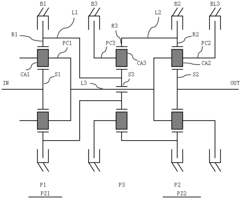


 400-4929-0909
 contact@catarc.com.cn

